Week 8 Challenge:Thermal Management
Introduction to Control of Electric Vehicle
Week 8 Challenge:Thermal Management
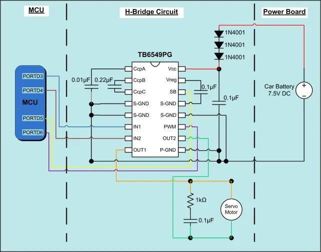
- Draw a high-level schematic of remote controller toy car system. What are the differences for an actual car?
Ans=>
How RC toys work
Radio-controlled or remote-controlled toys, popularly called RC toys, are self-powered and can be controlled from a distance using a remote that works with radio waves.
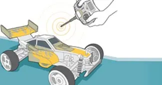
Radio-controlled or remote-controlled toys, popularly called RC toys, are selfpowered and can be controlled from a distance using a remote that works with radio waves.
- When we push the control, the transmitter sends a specific number of electrical pulses corresponding to that action through the air. The transmitter has its own power source, usually in the form of a 9-volt battery. Without the battery, the transmitter will not be able to send the radiowaves to the receiver.
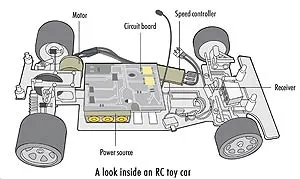
- Once the RC toy receives the radio waves, the motors kick into life to cause a specific action to occur. The power source sends power to all working parts, including the motor. The transmitter enables control through radio waves and the receiver activates the motors. When we press a button on the transmitter to make the RC toy go forward or backward, a pair of electrical contacts touch. Receiver
identifies signals, sends it to circuit.
- Circuit board translates the number of electrical pulses (signals) into action.
- The transmitter sends bursts of radio waves that oscillate with a frequency of 27,900,000 cycles per second (27.9 MHz), you will recognize this as pulse modulation.
- The truck is constantly monitoring the assigned frequency (27.9 MHz) for a signal. When the receiver receives the radio
bursts from the transmitter, it sends the signal to a filter that blocks out any signals picked up by the antenna other than 27.9 MHz. The remaining signal is converted back into an electrical pulse sequence.
- The pulse sequence is sent to the IC in the truck, which decodes the sequence and starts the appropriate motor. For our
example, the pulse sequence is 16 pulses (forward), which means that the IC sends positive current to the motor running
the wheels. If the next pulse sequence were 40 pulses (reverse), the IC would invert the current to the same motor to make
it spin in the opposite direction.
- The motor's shaft actually has a gearon the end of it, instead of connecting directly to the axle. This decreases the
motor's speed but increases the torque, giving the truck adequate power through the use of a small electric motor!
- The truck moves forward.
Parts of an RC toy

Transmitter: The remote control contains a radio transmitter which
operates on a particular frequency that the receiver is designed to receive.

The majority of RC toys are labeled with the frequency range they operate in. For example, the RC truck below has a label
designating it as a 27-MHz model.
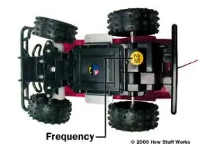
Transmitters range from single-function simple controllers to full-function controllers with a wide range of options. An example
of a single-function controller is one that makes the toy go forward when the trigger is pressed and backward when it is
released. To stop the toy, you have to actually turn it off.
Most full-function controllers have six controls:
- Forward: 16 pulses
- Reverse: 40 pulses
- Forward left: 28 pulses
- Forward right: 34 pulses
- Reverse left: 52 pulses
- Reverse right: 46 pulses
In most full-function controllers, not pressing any buttons or turning any knobs causes the toy to stop and await further
commands. Controllers for more advanced RC systems often use dual joysticks with several levels of response for precise
control.
Receiver: The receiver is fixed within the car and constantly receives
signals from the transmitter. When a transmission is identified, it
translates the number of electrical pulses into action.

Power source: All remote control cars require a power source.
Rechargeable batteries power small electric motors. Alternatively, some use small internal combustion engines.

Motor and Circuit Board: The motor is responsible for the turning
motions of the toy while the circuit board works like a pool through which all commands go on to specific parts.
Radio Control
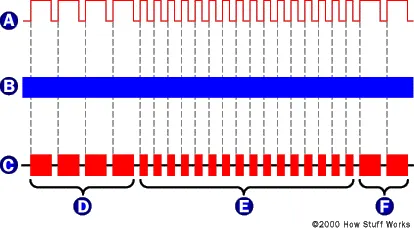
Here's the sequence of events that take place when you use the RC transmitter:
- You press a trigger to make the truck go forward.
- The trigger causes a pair of electrical contacts to touch, completing a circuit connected to a specific pin of an integrated
circuit (IC).
- The completed circuit causes the transmitter to transmit a set sequence of electrical pulses. Each sequence contains a short group of synchronization pulses, followed by the pulse sequence. For our truck,
the synchronization segment -- which alerts the receiver to incoming information -- is four pulses that are 2.1 milliseconds
(thousandths of a second) long, with 700-microsecond (millionths of a second) intervals. The pulse segment, which tells
the antenna what the new information is, uses 700-microsecond pulses with 700-microsecond intervals.
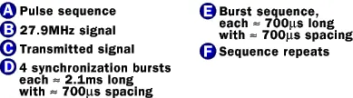
A typical RC signal transmission
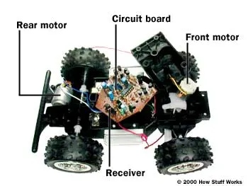
Inside an RC Truck
What are the differences for an a actual car?
=>
To make autonomous car many things change from RC toy car to actual car.Complete scenario of autonomous car of actual vehicle as follows,
First framed by SAE International (Society of Automotive Engineers) in 2014, these levels outline the degree of autonomy
of a self-driving vehicle.
Level 1Limited driver assistance. This includes systems that can control steering and acceleration/deceleration under specific
circumstances, but not both at the same time.
Level 2
Driver-assist systems that control both steering and acceleration/deceleration. These systems shift some of the
workload away from the human driver, but still require that person to be attentive at all times.
Level 3
Vehicles that can drive themselves in certain situations, such as in traffic on divided highways. When in autonomous mode, human intervention is not needed. But a human driver must be ready to take over when the vehicle encounters a situation that exceeds its limits.
Level 4
Vehicles that can drive themselves most of the time, but may need a human driver to take over in certain situations.
Level 5
Fully autonomous. Level 5 vehicles can drive themselves at all times, under all circumstances. They have no need for manual controls.
Progress to date
As of 2016, few companies have claimed to be at Level 2, including:
Tesla Autopilot
Volvo Pilot Assist
Mercedes-Benz Drive Pilot
According to Audi, the 2018 Audi A8 is claimed to be the first car to achieve level 3 autonomy with its AI traffic jam pilot.
Meanwhile, Waymo has already been running their level 4 autonomous cars in Arizona since mid-October 2017.
You can expect to see many more announcements in the coming months and years as the rest of these commercial efforts advance through these self-driving car levels.
The technology behind self-driving cars
The architecture of the autonomy system of self-driving cars is typically organized into two main parts:the perception system
the decision-making system.
The perception system is generally divided into many subsystems responsible for tasks such as: -self-driving-car localization
-static obstacles mapping
-moving obstacles detection and tracking
-road mapping
-traffic signalization detection and recognition
The perception system is also responsible for determining the state (position, speed, direction, etc) of the car at any given
point of time using the input from various sensors.
The decision-making system is commonly partitioned as well into many subsystems responsible for tasks such as:
-route planning
-path planning
-behavior selection
-motion planning control
The decision making system is also responsible for taking the car from one position to another, considering the state of
the system as well as the current traffic rules. In order to make such decisions, the decision-making system needs to
know the position of the car and its environment.
Modules within a typical self-driving car architecture:
-The Localizer module is responsible for providing the decision making system with the location. It makes use of offline
maps, sensor data, and platform odometry to determine the position of the car.
-The Mapper module produces a merge of information present in the Offline Maps and an occupancy grid map computed
online using sensors’ data and the current State.
-The Route Planner module computes a route from the starting position to the goal defined. The path planner then
computes a set of paths. A route is a collection of waypoints whereas a path is a collection of poses. A pose is a coordinate pair in the Offline Maps, and the desired car’s orientation at the position defined by this coordinate pair.
-The Behavior Selector module is responsible for choosing the current driving behavior, such as lane keeping, intersection
handling, traffic light handling, etc.
-The Motion Planner module is responsible for computing a trajectory from the current car’s state to the current goal,
which follows the path defined by the Behavior Selector module, satisfies car’s kinematic and dynamic constraints, and
provides comfort to the passengers.
-The Obstacle Avoider module receives the trajectory computed by the Motion Planner and changes it (typically reducing
the velocity), if necessary, to avoid collisions.
-Finally, the Controller module receives the Motion Planner trajectory, eventually modified by the Obstacle Avoider, and
computes and sends commands to the actuators of the steering wheel, throttle and brakes in order to make the car
execute the modified trajectory as best as the physical world allows.Sensors used by self-driving cars
-LIDAR
LIDAR, or Light Detection And Ranging, is used to measure the distance to a target by emitting pulsed laser light and
measuring the reflected pulses using a sensor. Combining inputs from multiple LIDAR modules around the car can be
used to create an accurate map of its surroundings.
After the invention of laser in 1960, LIDAR was first tested on airplanes using downward facing lasers to map the ground
surface. But it was only in late 1980s in which LIDAR measurements became reliable, when it was combined with GPS readings and inertial measurement units (IMUs). Point Cloud Image from a LIDAR
RADAR
Radar (RAdio Detection And Ranging) modules are also commonly used in self-driving cars. They work almost the same way as a LIDAR — the major difference is that radar uses radio waves rather than lasers.
Radar was developed for the military back in 1930s to detect aggressors in the air or on the sea. Aircraft and missile
detection is still one of the main uses of radar. It is also widely used in air traffic control, navigation systems, space
surveillance, ocean surveillance and weather monitoring.
Cameras
Most self-driving cars utilize multiple cameras for mapping its surrounding. For example, a Tesla has 8 cameras around
the car which gives a 360-degree view. This enables the Tesla vehicle to have full automation without requiring the help of
other sensors.
Unlike LIDAR, cameras can pick up lane markings, traffic lights, road signs and other signals, which gives a lot more information for the car to navigate on roads.
Video from Tesla’s website showing autonomous driving alongside different camera feeds.
Most self-driving cars use a combination of sensors and cameras, but with machine learning and computer vision playing a major role in self-driving technology, cameras are going to be the main component and might even replace other sensors completely over time.
Deep Learning for self-driving cars
As we know already, cameras are key components in most self-driving vehicles.Most of the camera tasks fall into some type of computer vision detection or classification problem. Recent advancements in deep learning and computer vision can enable self-driving cars to do these tasks easily.
Lets look at a deep learning pipeline by NVIDIA called DAVE-2, described in the paper ‘End to End Learning for Self-Driving
Cars’. The paper describes a convolutional neural network which is trained to map raw pixels from the camera feed to
steering commands for the vehicle.
Network Architecture
The model consists of 5 convolutional layers, 1 normalization layer and 3 fully connected layer. The network weights are
trained to minimize the mean-squared error between the steering command output by the network and the ground truth.
This convolutional neural network (CNN) has about 27 million connections and 250 thousand parameters.
Data Collection
The training data is the image feed from the cameras and the corresponding steering angle.
The data collection is quite extensive considering the huge number of possible scenarios the system will encounter. The
data is collected from a wide variety of locations, climate conditions, and road types. Also, training with data from the
human drivers is not enough. The network should learn to recover from mistakes otherwise the car might drift off the
lane.
In order to solve this problem, the data is augmented with additional images that shows different positions where the car
is shifting away from the center of the lane and different rotations from the direction of the road. For example, the images
for two specific off-center shifts from the left and right cameras and the remaining range of shifts and rotations are
simulated using viewpoint transformation of the image from the nearest camera.
The collected data is labelled according to road type, weather conditions, and driver’s activity. The driver could be staying
on lane, changing lane, turning and so on.
In order to train a convolutional neural network (CNN) that can stay on lane, we take only the images where the driver is
staying on lane. The images are also down-sampled to 10 frames-per-second (FPS), as many of the frames would be
similar and wouldn’t provide more information for the CNN model. Also, to avoid a bias towards driving straight all the
time, more frames that represent road curves are added to the training data.
Training
In order to train the model, data from three cameras as well as the corresponding steering angle is used. The camera
feeds and the steering commands are time-synchronized so each image input has a steering command corresponding to
Training the neural network
Images are fed into the CNN model which outputs a proposed steering command. The proposed steering command is
then compared with the actual steering command for the given image, and the weights are adjusted to bring the model
output closer to the desired output. Once trained, the model is able to generate steering commands from the image feeds
coming from the single center camera.
The trained network is used to generate steering commands from a single front-facing center camera.
Evaluation
The trained model is evaluated in two steps, first in simulation and then in on-road tests.
Simulation Tests
The computer simulation uses a library of recorded video footage from cameras and their corresponding steering
commands and renders images that approximate what would appear if the model was steering the car.
Using the simulation test, an autonomy score is determined for the trained model. The autonomy metric is calculated by
counting the number of simulated human interventions required. An intervention occur when the simulated vehicle drifts
off the center of the lane by more that one meter. An average of 6 seconds is considered for a real life human intervention
where they have to regain control of the vehicle and bring it back to the center of the lane.
So the autonomy score is calculated as:
So, if we had 10 interventions in 600 seconds, the autonomy score would be 90%:
Deploying to a Vehicle for Testing
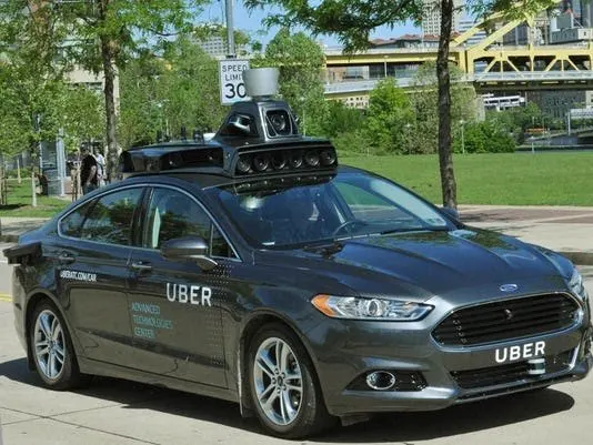
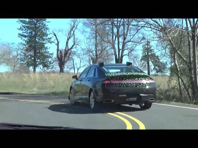
Once the trained model achieves good performance in the simulator, it is loaded on the DRIVE PX in the test car.
Q.2 What are the cooling requirements of a power converter? Take an example system and assume efficiency and other parameters. Suggest suitable solution to keep temperature below limit.
=>
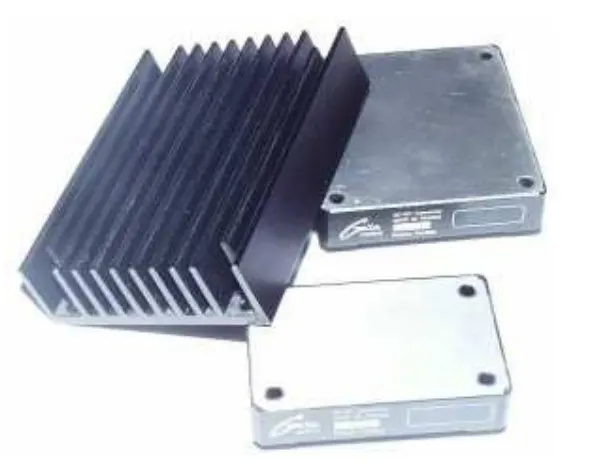
As with any power electronic circuitry, DC/DC converter do not transform all input power to output power; a portion of input power is dissipated as heat. The amount of heat dissipated is dependent on the output load and converter efficiency. The control and
evacuation of this heat is called thermal management.
Reasons for thermal management include :
- Maintain DC/DC converter case
temperature below maximum admissible
temperature
- Improve reliabilty (MTBF)
- Maximize efficiency
- Utilize maximum available output power
1-1 Power Dissipation in the DC/DC
pation & Efficiency
To calculate how much power is dissipated in the converter, input voltage, output power together with DC/DC converter efficiency must
be known.
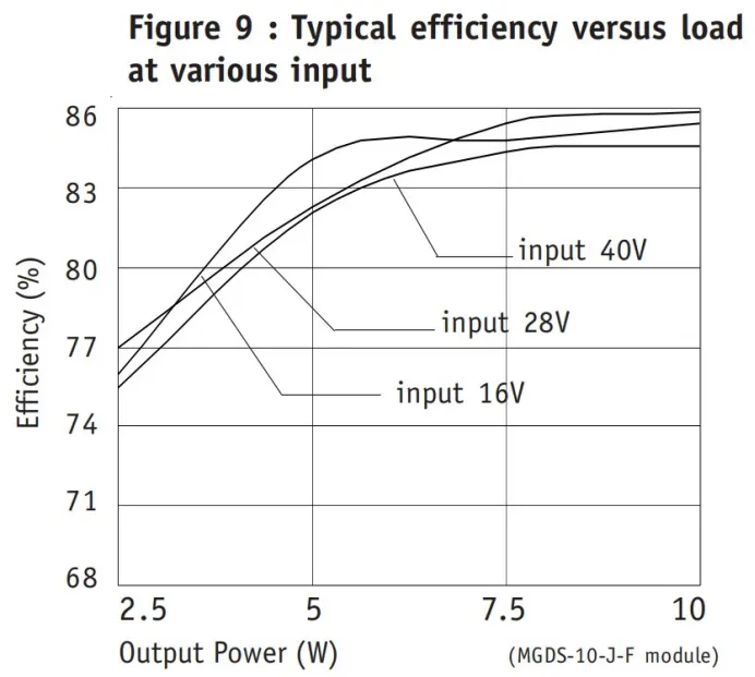
Example : the power dissipated in this
MGDS-10-J-F module at 28Vdc input voltage
and used at full load power 10W is :
the efficiency of this module at full load 10W
and 28 Vdc input voltage is 86%).
The power dissipation is a function of the power
used and DC/DC converter efficiency :
P-diss = (P-used/Efficiency - P-used)
In this example we find : Pdiss=1.6 W
This power dissipated is transformed into heat.
1-2 Heat Transfer
The primary goal in the thermal design is to predict and control the converter’s heat so that it does not exceed the maximum rating of temperature admissible by the DC/DC converter.
Heat energy is transferred from regions of high temperature to regions of low temperature via three basic mechanisms :
- radiation : electromagnetic transfer of heat between masses at different temperatures
- conduction : transfer of heat through a
solid medium (heatsink for example)
- convection : transfer of heat through the
medium of fluid (typically air from ventilation).
All three of these heat transfer mechanisms are active to some degree in every application. All three of these mechanism should be
given consideration when developping thermal management.
2-Radiation Transfer
Thermal radiation is the transfer of heat by electromagnetic
radiation (primarily in the infra-red wavelengths). Radiation is the only means of heat transfer between bodies
separated by a complete space vacuum.
Many factors contribute to thermal radiation efficiency,
such as temperature differentials, surface area, and surface emissivity.
Black anodized aluminum is a good thermal medium to
take advantage of radiated heat.
A heatsink with a large area for a given volume will take
maximum advantage of radiation.
But radiation is a minor contributor to the overall thermal
link in most power converter applications and counts in
majority of cases for less than 5% of total heat transfer.
It is best to use the effects of radiation as a «safety
margin» in the thermal design, since its contributions to
heat transfer will normally be small, is difficult to quantify,
and requires a relatively larger heatsink area to be efficient.
3-Conduction Transfer
3-1 General
Heat is transferred through a solid medium by conduction
and it is the most fundamental of all thermal mechanisms.
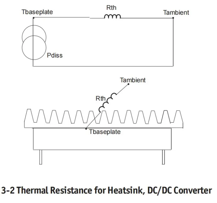
Thermal conduction can be understood as analog as
conduction of electrical current in a wire. As the electrical
current in a wire is a function of the different electrical
resistances and the voltage drop, the thermal transfer is
a function of the different thermal resistances and
temperature drop from one point to another.
This helpfull modelisation can be depicted as follow :
The thermal resitivity of a uniform conducting membrane
can be defined as: Rth = L / K x A
where :
Rth = Thermal Resistance (°C / watt)
L = Length or width (inch) or (mm)
A = Cross Sectional Area (inch2) or (mm2)
K = Material Thermal Conductivity (watt/inch°C or mm°C)
4-Convection Transfer
Heat transfer by Convection (Natural or Forced) involves
the transfer of heat to a surrounding fluid by conduction,
typically air. This mode of heat transfer is dependent on a
number of variables and is somewhat complex to calculate.
Surface area, temperature gradient, thermal conductivity
of fluid (air), velocity of fluid (air), fluid (air) density and
other variables affect convection.
4-1 Natural Convection
Natural convection is sometimes also referred as Free convection. Natural convection is easier to implement than
forced convection, but at the expense of increased thermal resistance.
Natural convection produces its own air velocity, due to
the local heating of air at the heatsink surface. The air
density is reduced when heated, causing it to rise, thus
causing the air movement.
Natural Convection is not as effective at higher altitudes
due to air density reduction.
«Free air» movement across a thermal dissipator is required
to perform adequately.
«confined air» would not conduct to natural convection.
This would occur with a converter mounted (without thermal contact) within an enclosed box.
To maximize the transfer of heat by natural convection
the following rules apply :
- Mount heat sinks so the maximum length of
convection surfaces (fins) are in the vertical plane.
- Place the heat sink above the converter, allowing air
to rise above.
- Provide sufficient enclosure ventilation for natural
convection of the air.
- Note that close heatsink fin spacing will reduce the
effectiveness of the heatsink.
Due to the complexity to calculate heat transfer for only
free air convection, majority of DC/DC converter
manufacturers or heatsink manufacturers are given their
thermal resistance performances in free air convection
condition (which will then include conduction and natural
convection).
4-2 Forced Convection
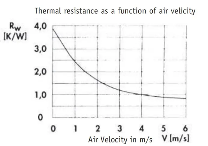
Forced convection implies the use of fans to increase the
air movement across the heatsink area. Heatsink to air
thermal resistivity can be improved by as much as a factor
of 10 when compared to natural convection.
This may be the way to go when operating at high ambient
temperatures, operating at high power levels, or when
space is at a premium. Of course fans are not without
their problems. They are noisy, and in dirty environments
they often require filters.
They can also cause an unreliable power system if the
filters are not changed frequently or the fan itself fails.
Therefore proper care must be exercised when fans are
used.
Conclusion:
Proper Cooling Of Power Converters Improves
Performance, Reliability .A high-density dc-dc converter can deliver substantial power, but only if excessive heat is removed by transferring internal heat through a number of material interfaces to a surface exposed to the surrounding air.
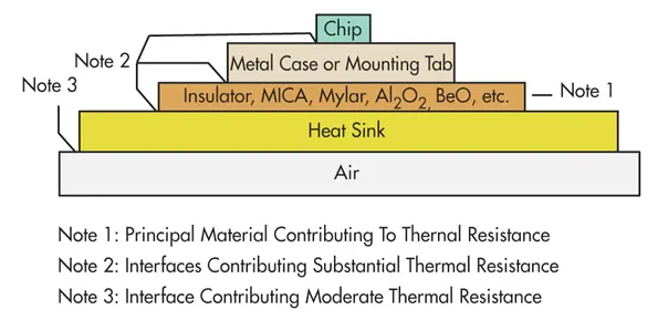
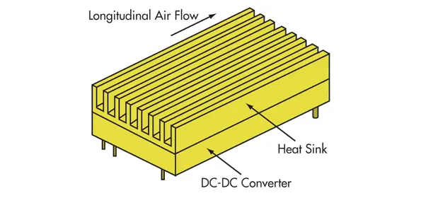
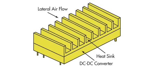
Fig. Finned heat sink for lateral airflow.
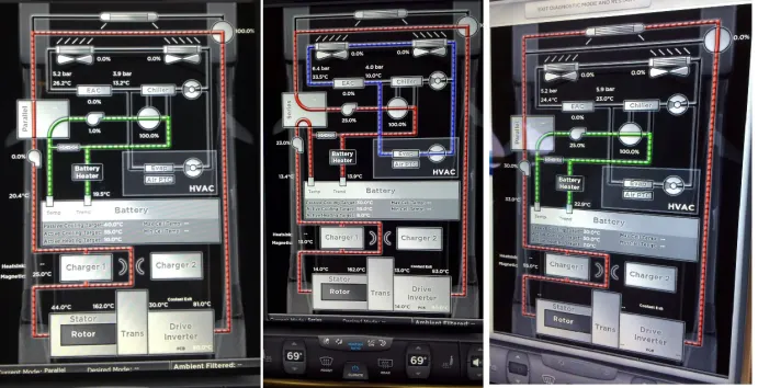
Q.3 Refer to below link and estimate thermal management system power requirement.
=>
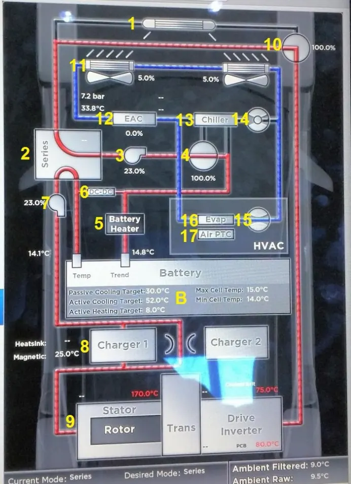
- Main coolant radiator.Does not have a fan. When vehicle is moving, air passes through cooling the Coolant. Coolant enters from the right. This radiator can be bypassed with device#10. This radiator, as when temperatures are very cold, bypassing the radiator will keep your battery and battery and motor from cooling further rather than warming up.
- Coolant circulation mode selector. A device that switches between two modes: Series and Parallel.If in series, coolant passes from #1 to #3 and then from B(Battery) to #7 and other loop from B to #3.
- 12V coolant pump. The %indicate pumps running speed. Slower pump speed uses less energy, prolongs pump life and slows the coolant flow. Full speeds are generally used during supercharging to maintain cooling to batteries.
- Adjustable coolant redirection valve. Sends 100% of coolant from #3 to #5, 100% from #3 to #13 or anything in between. Thermal management will determine this based on ambient temperature, battery, cabin, and motor temp.
- Coolant heater. Model S and X are rated for 6KW through can also run at 3KW. The coolant heater is a resistive heater that Runs on high voltage. Once activated, coolant will be warmed, and begin to flow through the battery pack. This is used to heat the Battery fast. Heat generated by #6#8#9 can also be used to for pack heating, through the use of those devices waste heat. Through that heating is minimal due to efficiencies of those units. A Cold pack will also cool down those devices. The coolant Heater can be “disabled” by activating the Model S or X Range Mode. The Coolant Heater will bring the battery up to 32*F/0*C or slightly higher to allow Regen and Charging. If Range Mode is turned ON, the coolant heater will not come on until approximately -10*F or -23*C, saving a considerable amount of power if charging or regeneration is not needed(In general, you will save more power than regen will gain you back by disabling pack heater). Plugging in the car and starting charging will over-ride range mode setting and heat pack to needed temperature. It will draw power from grid to pack while plugged in.
- DC-DC converter.Takes energy from high voltage pack, and steps it down to 12V (High voltage pack is 350-404V fully charged depending on battery & trim level). This 12V battery charged and all 12 V devices powered up. A more limited amount of coolant is directed through unit, as heat generation is low, and power output of this device is variable(So only what is needed is converted, thus reducing heat build up).
- 12V Coolant pump. This pump is required to keep the second loop of coolant flowing #2 is in parallel mode. Acts as a backup to #3. In series mode both pumps run at equal speed. In parallel, pump run at speeds that’s required for that specific system’s cooling.