Week-11 Challenge: Braking
HEV CHALLENGE - 11 Braking
Q.1 ANS=>
For a defined driving cycle, calculate the energy required for braking.
EXTRA URBAN DRIVE CYCLE :
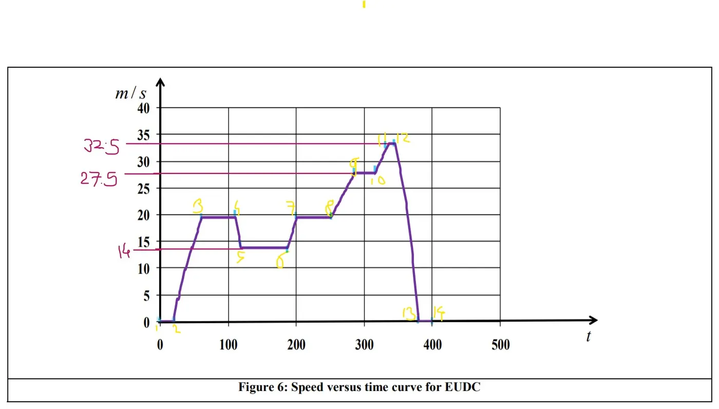
So, to calculate braking energy we consider 9 point i.e upto 300sec of drive cycle and calculate its braking energy during acceleration and decceleration.
Total braking energy = kinetic energy of vehicle
= K.E (due to linear motion) + K.E ( due to rotational motion)
But we here consider only kinetic energy due to linear motion for simplicity.
Here, let mass of vehicle (m) = 1000 kg
now take K.E between point,
Between point 1 & point 2=
Braking energy = (K.E)2 - (K.E)1=0 ......(As velocity is same=0 m/s)
Between point 2 & point 3=
Braking energy = (K.E)3 - (K.E)2
= (.5*m* v^2)3 - (.5 * m * v^2)2
= (.5 * 1000 * 20^2) - (.5 * 1000 * 0^2)
= 2,00,000 J
= 200 KJ
Between point 3 & point 4=
Braking energy = (K.E)4 - (K.E)3=0 .......(As velocity is same)
Between point 4 & point 5=
Braking energy = (K.E)5 - (K.E)4
= (.5 * 1000 * 14^2) - (.5 * 1000 * 20^2)
= -1,02,000 J
= - 102 KJ .........(Negative sign represents decceleration)
Between point 5 & point 6=
Braking energy = (K.E)6 - (K.E)5=0 .......(As velocity is same)
Between point 6 & point 7=
Braking energy = (K.E)7 - (K.E)6
=(.5 * 1000 * 20^2) - (.5 * 1000 * 14^2)
= 1,02,000 J
= 102 KJ
Between point 7 & point 8=
Braking energy = (K.E)8 - (K.E)7=0 .......(As velocity is same)
Between point 8 & point 9=
Braking energy = (K.E)9 - (K.E)8
= (.5 * 1000 * 27.5^2) - (.5 * 1000 * 20^2)
= 1,78,125 J
= 178.125 KJ
Between point 9 & point 10=
Braking energy = (K.E)10 - (K.E)9=0 .......(As velocity is same)
Thus Net Braking Energy during drive cycle=0 + 200 KJ + 0 + - 102 KJ + 102 KJ + 0 + 178.125 KJ + 0
= 378.125 KJ
So, we required 378.125 KJ of braking energy upto 300 sec of drive cycle .
Q.2 Ans.=>
Why electric motor can't develop braking torque at high speed similar to starting ?
⦁ It should be noted that the maximum regenerative braking force produced by an electric motor is closely related to the electric motor’s speed.
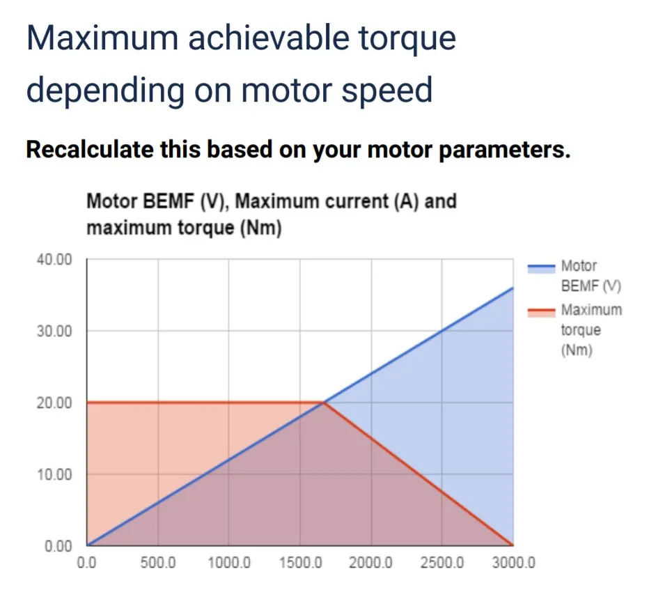
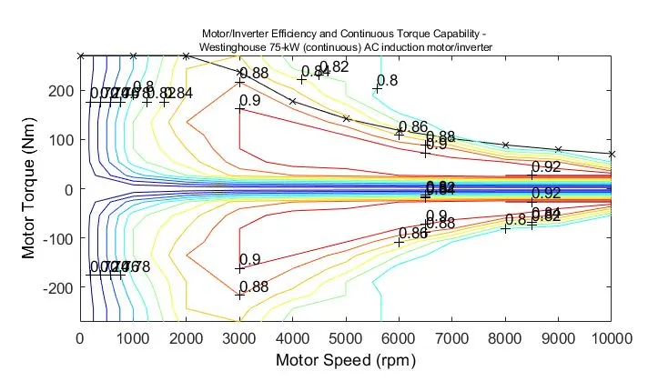
⦁ At low speed (lower than its base speed), the maximum torque is constant. However, at high speed (higher than its base speed), the maxing torque decreases hyperbolically with its speed. Therefore, the mechanical brake torque at a given vehicle deceleration varies with vehicle speed.
⦁ At high speeds, the Back EMF is so close to Vbus that the applicable Motor torque gets limited. Then, the bigger the Friction torque + Additional load is, the smaller the Acceleration torque becomes.
⦁ Peak Acceleration Torque and Peak Deceleration torque are not equal for Electric Vehicle Motor.
⦁ Acceleration is usually higher, at low speed we get higher Torque but high speed the value of the torque gets lower.
⦁ As at starting of acceleration of motor we have peak constant torque of 7 Nm but when we cross base speed so at these high speed if driver want to apply brake then motor must produce negative torque and that value if plotted is not same as acceleration torque at starting, we get less than -7 Nm around -4 Nm say. This happen beacause motor is in Field Wakening region. So we have to compromise on torque.
⦁ Thus , Electric motor can’t develop braking torque at high speed similar to starting, because Braking Torque of an electric Motor is not as high as the Acceleration Torque.
How electric motor and mechanical brakes are coordinated?
- REGENERATIVE(Electrical) AND MECHANICAL(frictional) BRAKES :
Regenerative braking is a key technology that improves the overall efficiency in electric vehicles (EVs) and hybrid electric vehicles (HEVs). During regenerative braking, the kinetic and potential energies of the vehicle are converted into electrical energy and stored in a battery or a supercapacitor for driving. Regenerative braking is more effective in city driving conditions, where the brakes are applied more frequently. Regenerative braking can improve the fuel efficiency of the vehicle from 20% to 50%, depending on the motor size.
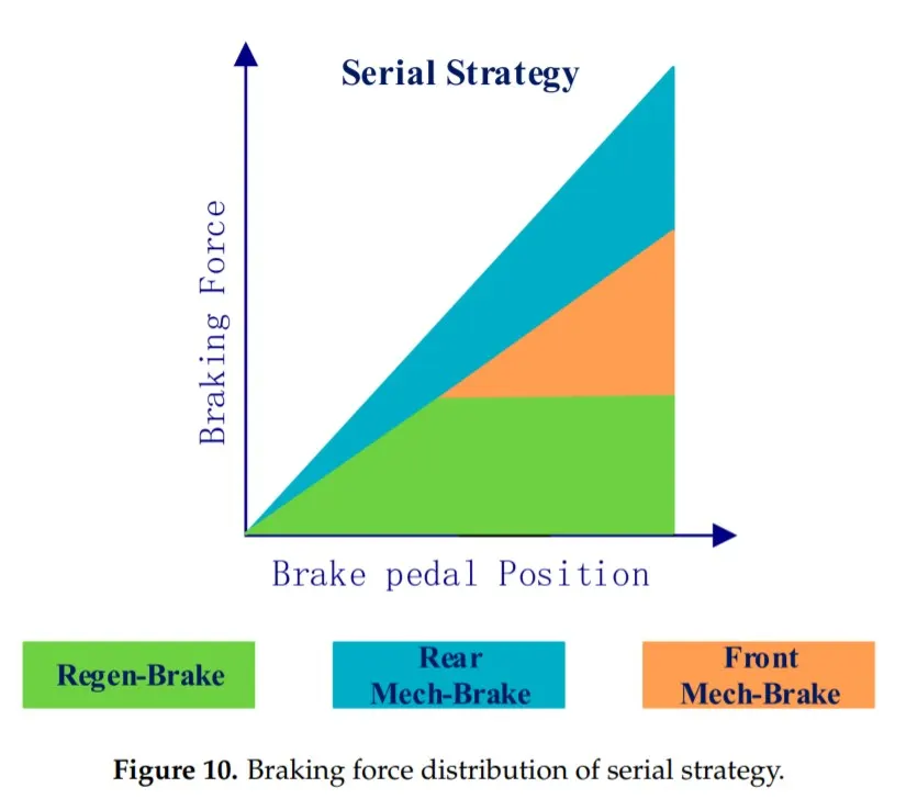
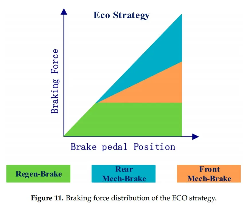
In most cases, the regenerative brake works together with the conventional friction brake to meet the total braking force demand. Under some conditions such as a high state of charge (SOC) of the battery or low-speed braking, the regenerative brake is limited and only the friction brake is applied. Hence, cooperative control of the regenerative brake and the friction brake is always required to generate an adequate braking force.- Further, the braking force is applied only on the driven wheels in regenerative braking. The non-driven wheels are not subjected to braking during the regenerative braking mode. For stable braking of any vehicle, the braking force distribution (BFD) between the front wheels and the rear wheels should balance the dynamic limit of the vehicle.
Another challenge in regenerative braking is the driver’s feel. In EVs and HEVs, the total braking force generated can be in three modes: the friction brake mode, the regenerative brake mode and a combination of the two. In all modes, the driver should have the same feel (in terms of the vehicle deceleration) for a given brake pedal displacement.
The regenerative braking configuration can be broadly classified into series braking and parallel braking.
In series braking, cooperative control of the friction brake and the regenerative brake is achieved by the vehicle controller together with the motor controller and the friction brake controller. In series braking, the regenerative brake is mostly applied first before the friction brake.
The parallel regenerative braking system is relatively simple; the energy recovered by the regenerative braking system will be small, and the driveability of the vehicle may be affected. In conventional parallel braking, both the friction brake and the regenerative brake are applied in parallel, and no cooperative control takes place between the friction brake and the regenerative brake.
The vehicle controller controls only the regenerative braking torque, whereas the friction braking torque is controlled directly by the brake pedal displacement in parallel braking. This type of configuration is used in EVs or HEVs which have a mechanically controlled friction brake.
Since EVs and HEVs in emerging markets such as India have a mechanically controlled friction brake, where the series braking configuration cannot be adapted because of its high cost, parallel braking is a feasible solution. However, conventional parallel braking has a low energy regeneration capability. Hence, improving the energy regeneration in conventional parallel braking is improved to solution called ‘combined braking’ is proposed, which can double the energy regeneration in comparison with that of conventional parallel braking in EVs or HEVs which have a mechanically controlled friction brake.
Combined braking :
The main objective of the proposed combined braking system is to regenerate the maximum energy in an EV or an HEV which is equipped with a mechanically controlled friction brake system.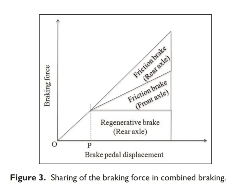
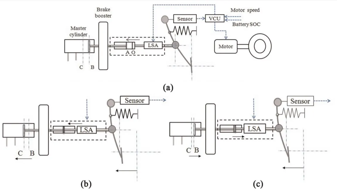

- System description. :Figure 4(a) provides the schematic layout of the proposed combined braking concept which consists of standard components such as the brake pedal, the brake booster, the master cylinder and the pedal travel sensor. In addition, a linear solenoid actuator (LSA) was introduced between the brake pedal and the brake booster, and it is controlled by the vehicle controller. The LSA performs the following two basic functions.
1. It creates a predefined gap (OA in Figure 4(a)) between the brake pedal and the brake booster to delay the actuation of the friction brake in response to the driver’s brake demand through the application of the brake pedal. The actuator displacement equivalent to the gap OA is termed the ‘idle actuator displacement’ and the pedal travel equivalent to OA is termed the ‘idle pedal displacement’.
2. While braking is in progress, it regulates the friction braking force by controlling the displacement (BC in Figure 4(a)) of the master cylinder plunger.
During normal driving conditions, the actuator is retracted such that it maintains the predefined gap OA between the actuator and the brake booster. During the actuator displacement equivalent to OA, the brake booster and the master cylinder are not actuated to apply the friction brake.
The displacement of the actuator beyond OA creates a mechanical contact between the actuator and the booster; because of this, the actuating force is transferred to the master cylinder to apply the friction brake. In the case of any failure in the signal or the supply current to the solenoid actuator, the compressed spring inside the actuator will return the actuator plunger to a fail-safe position, which will close the gap OA. This ensures that the conventional friction brake is available as a secondary or emergency option.
- Flow chart for combined braking:
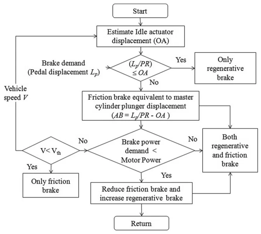
The idle actuator displacement OA equivalent to Li is
given by OA = Li/PR , where PR is the pedal ratio.
Further, in this stage, braking can occur in two conditions as discussed in the following.
- Condition 1: pedal displacement Lp <= idle pedal displacement Li. In this condition, only the regenerative brake is applied and the master cylinder is not
actuated (thus, the friction brake is not applied). - Condition 2: pedal displacement Lp > idle pedal displacement Li. In this condition, the LSA comes into contact with the brake booster’s plunger and
actuates the master cylinder (Figure 4(b)), and both the regenerative brake and the friction brake are
applied. The master cylinder plunger is displaced by BC equivalent to the pedal displacement Lm.
- Common Regenerative Braking Strategies :
To understand the proposed braking strategies and braking performance concerns, a basic logical flow diagram is shown in Figure . When the brake pedal moves, the braking system analyses the brake safety situation and follows the selected braking strategy according to various regulations . Any occurrence of wheel lock triggers the ABS.
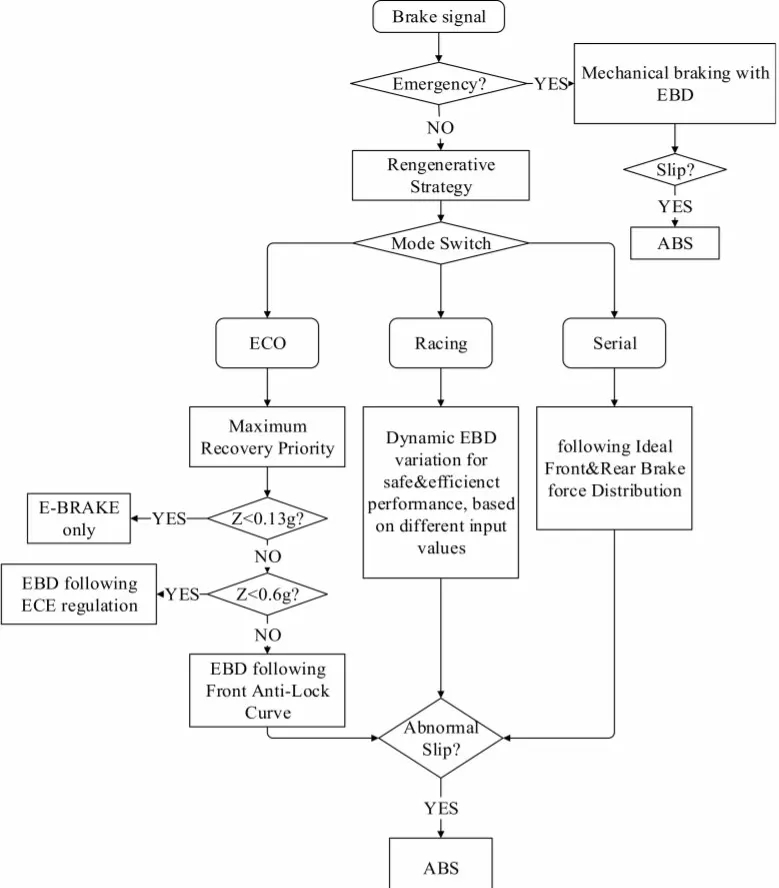
Figure : Upper frame of braking strategies for the regenerative braking system (RBS), electronic brakeforce distribution (EBD) and antilock braking system (ABS)
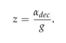
where, z= the braking intensity (z) is introduced, as follows:
Q.3 Ans.=>
To plot contour line for a given Motor.
A Motor have various types of losses happening inside. The various types of losses are
- Copper Losses -
I^2 ⋅ R, where R is the Armature resistance and we say that Torque is proportional to Current, this copper loss can be consider as kc⋅ T ^2 .where kc is to take care of resistance of brushes and also take care of flux and its effect.
Copper losses = kc ⋅ T^2
- Iron Losses -
Iron Losses are nothing but Magnetic losses, which is denoted as ki⋅ ω, where ki factor is based on the Magnetic field effect. For Permanent Magnets have constant Magnetic field and this Iron losses is based on the value of ki and this are going to change according to the Speed. At Various Speed have different value of Back EMF and that is going to affect the Iron Losses.
Iron Losses = ki ⋅ ω
- Windage Losses -
This is a Mechanical or friction of Windage losses. This is based on size of shape of Motor and the amount of windage losses that the motor is going to experience.
Windage Losses = kw ⋅ ω^3
- Constant Losses -
This is denoted as C.
Total Losses - The Total Losses are considering the above four losses and denoted as,
Total Losses = kc ⋅ T^2+ ki⋅ ω+ kw ⋅ ω^3 + C
All Motors are model as per the above equation of losses. This above equation is not only applicable for Permanent Magnet DC Motor, but other motors as well like induction motor.
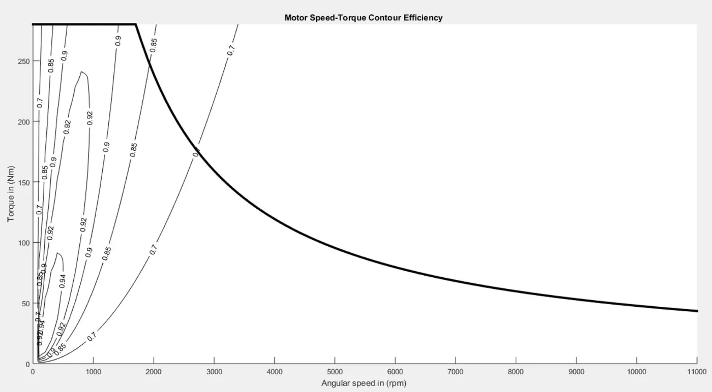
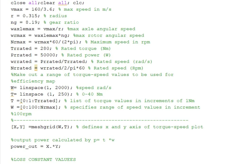
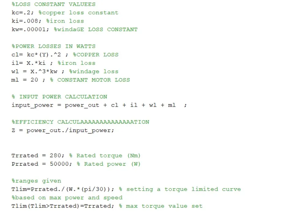
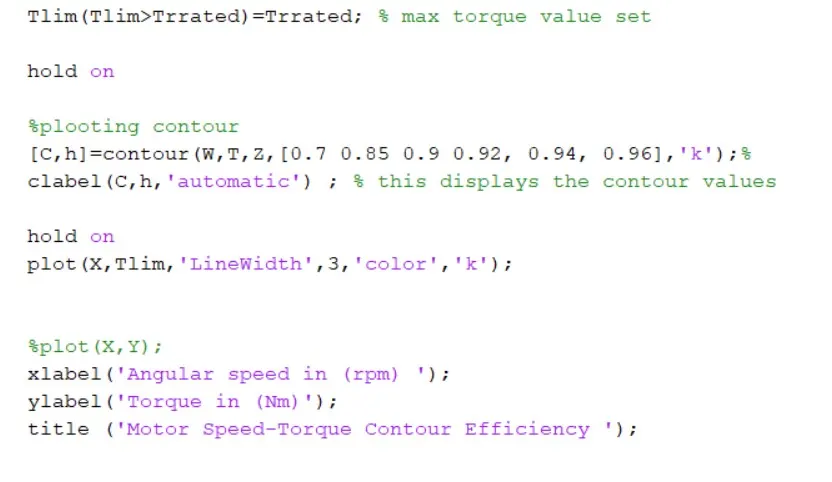
MATLAB Program to Plot Motor Speed-Torque Contour Efficiency :
Code :
Plot :