Week 8 Challenge
1. Calculate the loads as per IRC 6 assuming a bridge in Bangalore on the pile group of the below given bridge for the abutment.(ignore temperature and wind)
Load Calculation:-
All the loads acting on the abutment as per IRC 6 need to be determined for a single span.
- cross-sectional area of the section at support - 7.901 Sqm ( Determined Form Auto CAD)
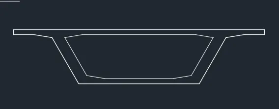
- The cross-sectional area of the section at Mid - 6.913 Sqm ( Determined Form Auto CAD)
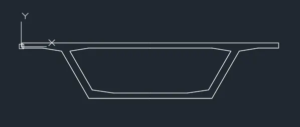
- Extend the length of the girder at the support section to 15.45 m
- Extend the length of girder at mid-section - 15.45 m
Given Data:-
Base design details
1 Basic design data
1.1 Span and cross-section data Left Span
c/c of expansion gap 30m
c/c of bearing 28m
Distance of bearing to expansion gap 1m
Girder overhang beyond bearing 0.35m
Total deck Width 12m
Carriageway width 11m
Crash Barrier Width 0.5 m
Width of Median 0
2 . SuperStructural details Left
Number of Griders 4
Spacing of Griders 3m
Cantilever on both sides 1.5m
Depth of Superstructures 1.32m
C.G of Superstructures 0.88m
Wearing coat thickness 0.065m
Distance of FRL from bearing of least height 10.9m
Bearing Thickness 0.25m
Pedestal Thickness 0.25m
Superelevation 2.50%
3. Levels
HFL 232.1
Bed Level 231.5
Road Level 232.361
Minimum vertical clearance needed 4 m from drg
Saffit Level 238.172
Pier cap top 237.672
Pier Top 237.072
Height of SubStructures 5.211m
Pile cap Top level 231.861
Pile cap bottom level 230.361
Depth of pile cap 1.5 m assume
Clear cover for foundation 75mm
Height of Substructures 5.5
4. Water Current Data
max. Mean velocity 0.98m/s
Constant "k" for the pier in the transverse direction 0.66
Constant "k" for the pier in the longitudinal direction 1.5
% of uplift considered 100%
5. Material used
Grade of Concrete M35
Design of Concrete 15.65Mpa
grade of Steel Fe500
The design strength of steel 434.8Mpa
The density of RCC 2.5t/m3
The density of wearing the coat 2.2t/m3
Coef. of thermal expansion of steel 1.2 E-05/c
Shrinkage strain of concrete 2.00E-04
Modulus of elasticity of steel 20000000mpa
Modulus of elasticity of concrete Ecm for M35 32000mpa
The mean axial tensile strength of concrete 2.8Mpa
The density of concrete is 2.5t/m3
The density of wearing the coat is 2.2t/m3
- Soil Parameters
The density of dry backfill 2t/m3
Density of submerged backfill 1 t/m3
Net SBC 25 t/m3
Gross SBC (LWL) 33.92 t/m3
Gross SBC(HFL) 27t/m3
Net sbc -seismic case 31.25t/m3
Gross SBC-seismic case 33.25 t/m3
Type of soil medium Soil
Partial Safety factor
Material Basic Combination Seismic Combination
Concrete 1.5 1.5
Reinforcement 1.15 1.15
Load on SuperStructure
Dead Load
Total weight of superstructure 199t
DL reaction 99.5t
Total Reaction on the abutment 99.5t
Unbalanced Long. Moment 0 tm
Transverse ecc. of DL from pier C/L 0 tm
Transverse moment due to unbalanced DL 0 tm
SIDL (Except WC)
Weight of Crash barrier 1 t/m
Weight of Crash barrier 60 t
Weight of median 0 t
Weight of footpath 0 t
Total reaction on the abutment 30 t
Total Long. Moment 0 t
Transverse ecc. of CB 0 t
Total Transe. Moment 0 t
SIDL (WC)
Load intensity due to WC 0.22 t/m2
Weight of WC 77.60 t
Total reaction on the abutment 36.30 t
Unbalanced long. Moment 0 tm
Transverse ecc. of WC 0 m
Transverse Moment due to unbalanced WC 0 tm
Substructure
Abutment
Length (Longitudinal) 12 m
Length (Transverse) 1.3 m
Height 0.3 m
Volume 4.68 m3
Weight 11.70 t
Trapezoidal Part
Top length 12 m
Bottom length 7 m
Top width 13 m
Bottom width 1.3 m
Height 0.3 m
Volume 3.66 m3
Weight 9.15 m
Total weight of Pier cap 20.85 t
Pier shaft
Dimension along traffic direction 1 m
Dimension perpendicular to traffic 7 m
The area of the rectangular part 7 m2
Height 5.50 m
Volume 38.50 m3
Area - semicircular 0 m2
Height 5.50 m2
Volume 0 m3
Weight of Pier 96.25 t
Total weight of structure 117.10 t
Foundation
Type Foundation Pile
The diameter of pile 1 m
No of the pile in each direction 3 nos
Spacing of pile in each direction 3
Size of pile cap 7.3*7.3 m2
The thickness of the pile cap 1.5 m
weight of pile cap 199.84 t
Weight of soil on pile cap
Road level 232.361
Pile cap top level 231.861
Depth of soil above pile cap 0.5 m
The total volume of footing 26.645 m3
Total weight of footing 53.29 t
Live Load
1 Lane 70R wheeled
Live Load Reaction
Total live load 100 t
No of lanes 3 lanes
% reduction in live load 10%
Impact factor - 1L 70R 1.13
Ra 75.3 t
Rb 26.4 t
Vertical reaction on the abutment 75.3 t
Braking force 20% of Ra = 20%*75.3=15.06 t
Total Horizontal force at bearing level Fh/2 = 7.53 t
Longitudinal moment 75.3 tm
Bearing Type POT, PIFE
Transverse eccentricity 3.405 m
Transverse Moment 256.40 tm
1 Lane Class A
Live Load Reaction
Total live load 55.4 t
No of lanes 3
% reduction in live load
Impact factor - 1L 70R 1.125
Ra 39.88 t
Rb 7.967 t
Vertical reaction on the abutment 3.988 t
Braking force 39.88 tm
Total Horizontal force at bearing level 3.988 t
Longitudinal moment 39.88 tm
Bearing Type
Transverse eccentricity 4.7 m
Transverse Moment 187.44 tm
3 Lane 70R wheeled
Ra 119.64 t
Rb 48.63 t
Vertical reaction on the abutment 119.64 t
Braking force 17.94 t
Total Horizontal force at bearing level 8.97 t
Longitudinal moment 119.64 tm
Bearing Type
Transverse eccentricity 1.2 m
Transverse Moment 143.57 tm
Summary
| Live load Case | Vertical Load in t | ML in tm | MT in tm | HL in t | HT in t |
| 1lane 70R wheeled | 75.3 | 75.3 | 256.4 | 7.53 | 0 |
| 1L class A | 39.88 | 39.88 | 187.44 | 3.98 | 0 |
| 3L class A | 119.64 | 119.64 | 143.57 | 8.97 | 0 |
Summary
| Load CAse | Load P t | ML tm | MT tm | HL t | HT t |
| DL | 99.5 | 0 | 0 | 0 | 0 |
| SIDL | 30 | 0 | 0 | 0 | 0 |
| SIDL(WC) | 36.3 | 0 | 0 | 0 | 0 |
| Weight Substructure | 117.1 | 0 | 0 | 0 | 0 |
| Weight of pile cap | 199.84 | 0 | 0 | 0 | 0 |
| Weight of Soil above pile cap | 53.29 | 0 | 0 | 0 | 0 |
| LL1 | 75.3 | 75.3 | 256.4 | 7.53 | 0 |
| LL2 | 119.64 | 119.64 | 143.57 | 8.97 | 0 |
2) Well foundation:- Well foundation is a type of deep foundation that is generally provided below the water level for bridges.
The caissons are of three types:-
(i) Box cassion:- It is open at the top and closed at the bottom and is made of timber, reinforced concrete or steel. This type of cassion is used where bearing stratum is available at shallow depth.
(ii) Open cassion:-Open cassion is a box opened both at the top and bottom. It is made up of either timber, concrete or steel. The open cassion is called well. Well, foundation is the most common type of deep foundation used for bridges in India.
(iii) Pneumatic cassions:-Pneunmatic cassions have their lower end designed as a working chamber in which compressed air is forced to prevent the entry of water and thus excavation can be done in dry conditions.
Components of the well foundation:-
Cutting Edge:-It is the lowest part of the foundation well, and fabricated in the yard as per the approved drawing. Cutting edge shall be fabricated in a number of segments depending upon circumference and ease of handling and transport. Cutting edge helps to cut the soil during the sinking operation.
Well Curb:-The well curb is designed to support the weight of the well with partial support at the bottom of the cutting edge, i.e. when only part of the cutting edge is in contact with soil and the remaining portion is only held by skin friction.
Three-point support of the cutting edge resting on a log may be assumed for design purposes. The load coming on the cutting edge is uncertain as a considerable part of it is borne by skin friction.
Another factor of uncertainty is in regard to the effective depth of the well curb since the entire well acts as a deep girder to resist torsion and bending.
Since the load is occasional, working stress up to 99% of yield stress may be permitted. The well curb has also to withstand stress due to sand blows, as well as due to light blasting required when a boulder obstructs the sinking of the well.
Well Steining:-Steining is a wall or shall type of structure made up of RCC, and which helps to transfer the load to the curb. It serves as an enclosure for excavating the soil for the penetration of the foundation well.
Bottom Plug: After the completion of the sinking, the bottom of the foundation well is plugged with the help of concrete. The well curb confines the bottom plug and functions like a raft against soil pressure from below.
Back-filling:-The well is dewatered after the setting of bottom plug concrete, and it is backfilled by sand or excavated approved material. Sometimes water can be used instead of sand/excavated material.
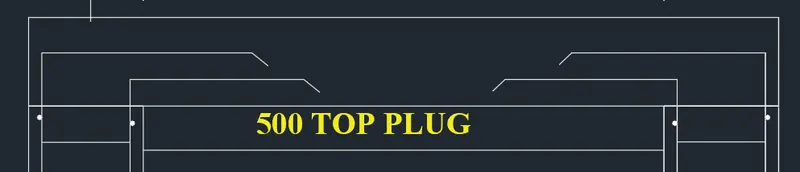
Top plug:-It is a concrete layer of thickness around 500mm, as mentioned in the design and drawing. Top plug provided over the filling and inside the well dredge hole.
Well cap:- A well cap is a thick concrete mat that rests on the top of the well stening. It is a part of the foundation and used to distribute loads of superstructure over the steining.
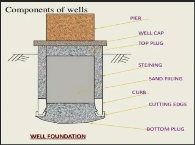
Component of Well Foundation
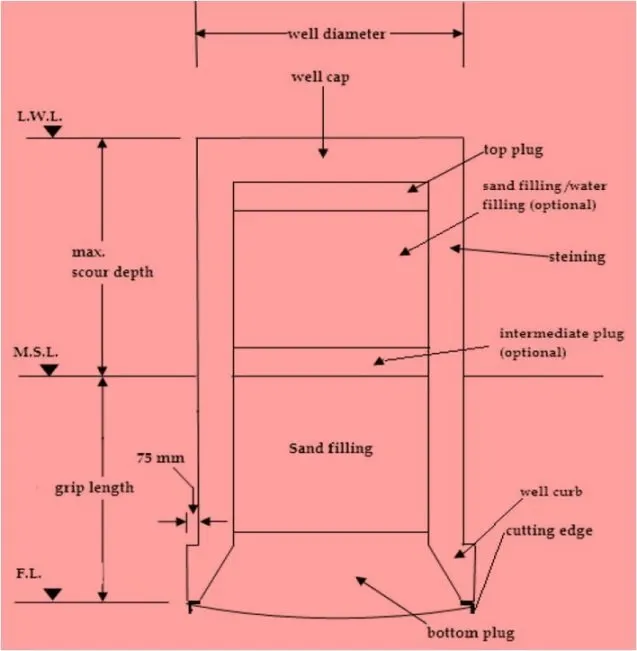
Section of Well Foundation
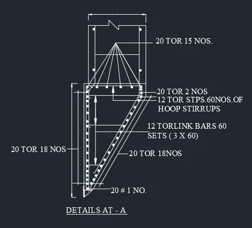
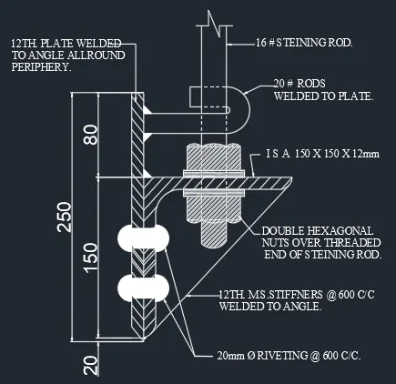
Bottom Plug
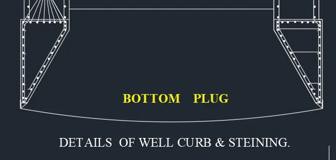
Top Plug