Week 8-Challenge
Aim:
The main plan is to create a volumetric mesh for the given components. The Given components are Housing, Chassis assembly component, and another Component. The goal is to use the different methods of tetra mesh to create a volume for the components given.
Methodology:
The methodology for this project is as follows:
- Opening the File.
- Checking and performing the Geometric Cleanup.
- Generating the Mesh (3D and If necessary 2D)
- Reducing Errors:
Theory:
Chassis:
Chassis is the main support structure of the vehicle which is also known as ‘Frame’. It bears all the stresses on the vehicle in both static and dynamic conditions. In a vehicle, it is analogous to the skeleton in living organisms. The origin of the word Chassis lies in the French language. Every vehicle whether it is a two-wheeler or a car or a truck has a chassis-frame. However, its form obviously varies with the vehicle type.
Procedure:
- Opening the File:
- The File opening does requires few steps to be followed which then results in the opening of the file.
- Go to the Files >> Import >> Geometry.
- Now Select the File you want to import.
- Select the File Type as “STEP” (The File format is ‘.stp’) and Click on Import by selecting the file again.
- If the File is didn’t appear click on the display panel and enter Keyword “F” and the component will be displayed.
- If the Model is of ‘.hm’ format just go to the Files>> Click Open >> Select the File >> Click Open.
- Generating the Mesh:
- The Volumetric Mesh is done for the component that follows three different methods in which the volume can be extracted. The methods are as follows.
- For Tetra Mesh, 2D surface mesh followed by the 3D Volume Mesh:
- Initially, after the file is opened. Check for the Geometry.
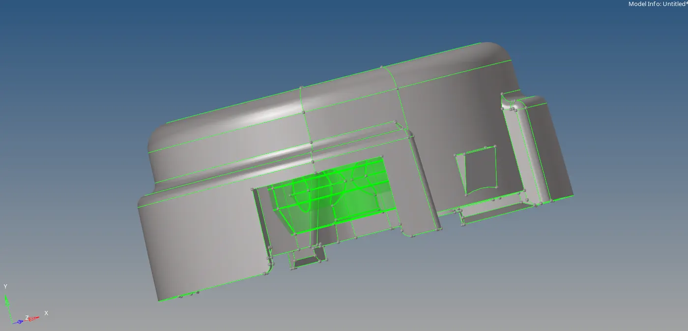
- If it is a solid delete it to create a surface.
- Click F2>> select Solids >> Select the Model >> Click on Delete Entities/ middle-click on the mouse.
- The surface of the component appears. The Quality criteria of the model should be given. Both the 2D and 3D should be given.
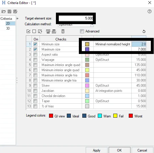
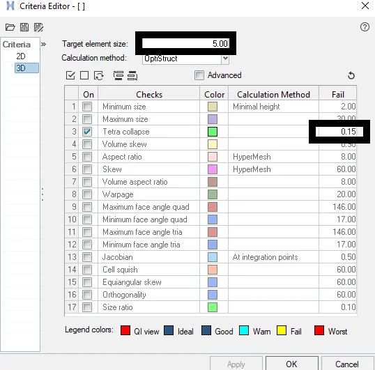
- The component needs to be meshed.
- For mesh, Click on 2D tab >> automesh >> select surfs option >> give element size as 5 (given Quality Criteria) >> Select Mesh type as Trias >> Click Mesh.
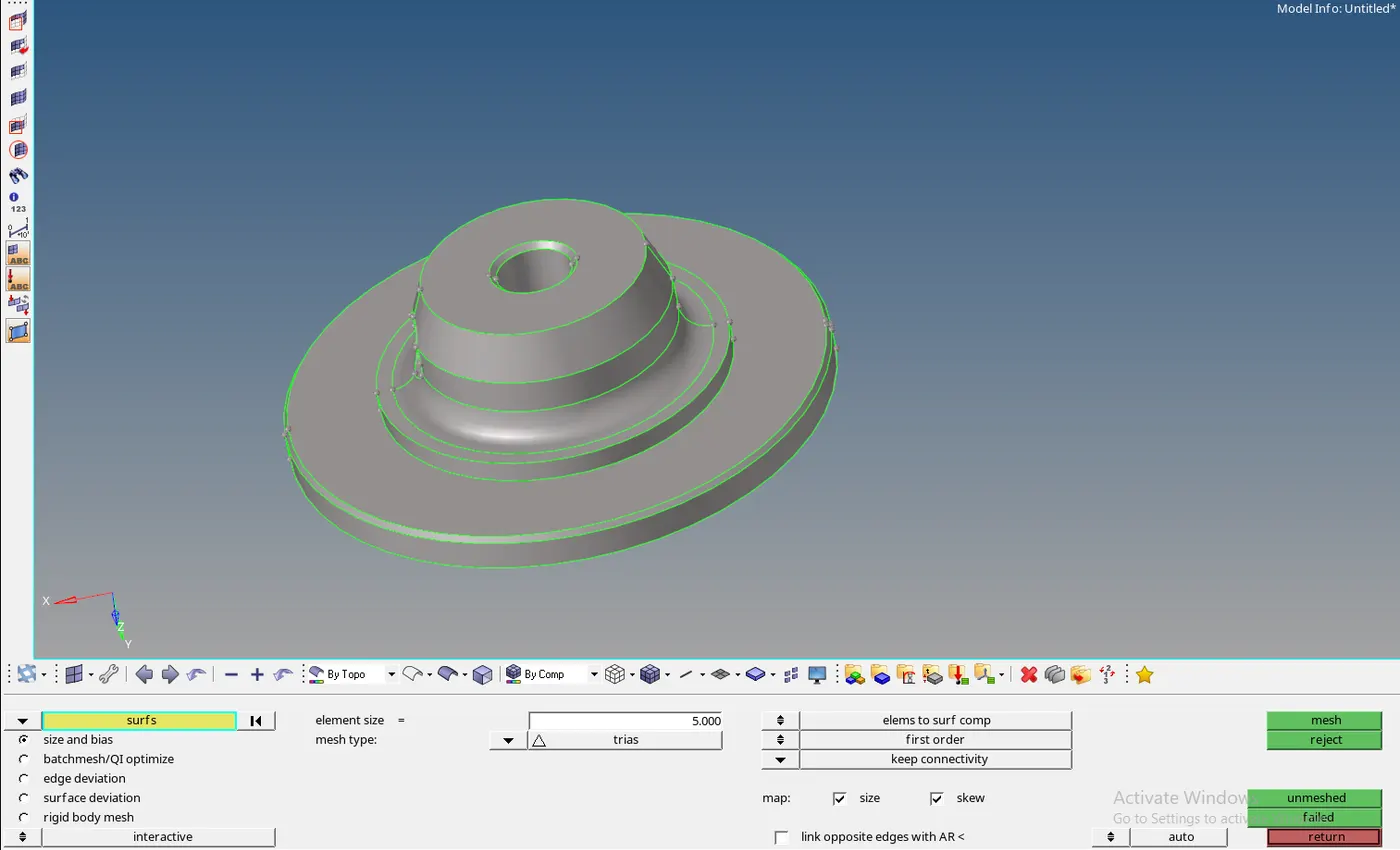
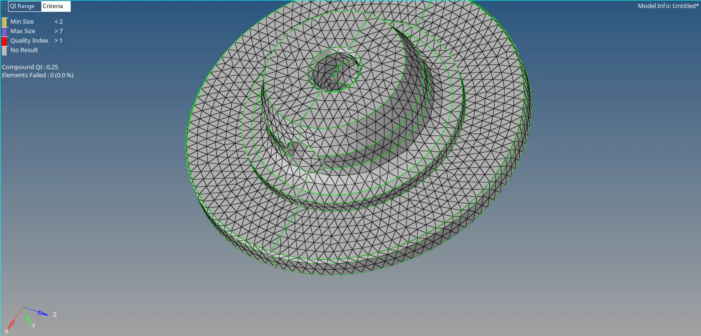
- Clean the errors faced during the mesh. Most of the errors will minimum and Maximum length errors.
- Once the mesh is done, 3D mesh needs to be done to get the volume of the given component.
- Before mesh, the meshing parameters need to be completed so that the mesh is completed within those parameters.
- Go to the 3Dpanel >> Tetra Mesh Tab >> Select tetra mesh parameters >> check the box of Maximum Tetra size, fill voids, fix mid nodes, smoothing boxes and, select the Minimum Tetra Size >> select element quality target as 15.

- Go to the 3Dpanel >> Tetra mesh tab >> select the component to be meshed >> Select fix comp boundaries, update input shells >> Click Mesh.

- The Solid Mesh is Created. The Mask Option is used to check if the solid is created or not. (Mask Tool hides the elements selected.)
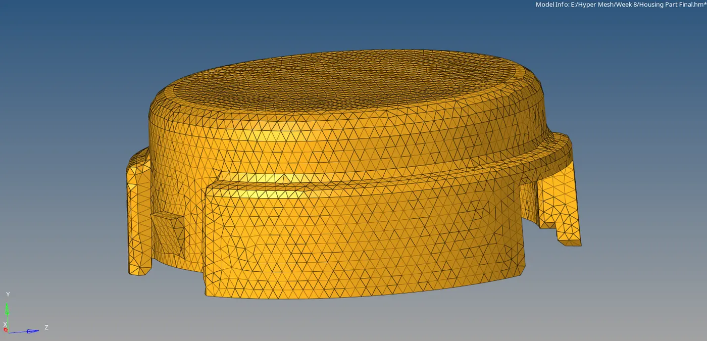
- Using Quick Tetra mesh:
- The second method used here is the Quick Mesh option.
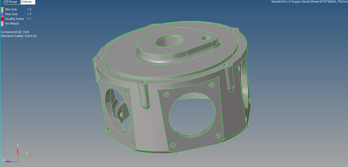
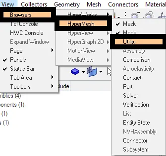
- Go to the View >> Browers >> Hypermesh >> Utility
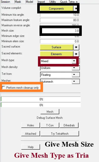
- Select Geom/Mesh >> click on quick Tetramesh. A new tab will be opened.
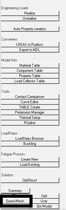 `rarr`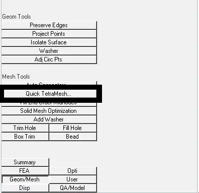
- Select the Components >> Give Mesh Size >> give Minimum element size >> Give Mesh Type as Trias>> Check mesh cleanup only box >> Click Mesh.
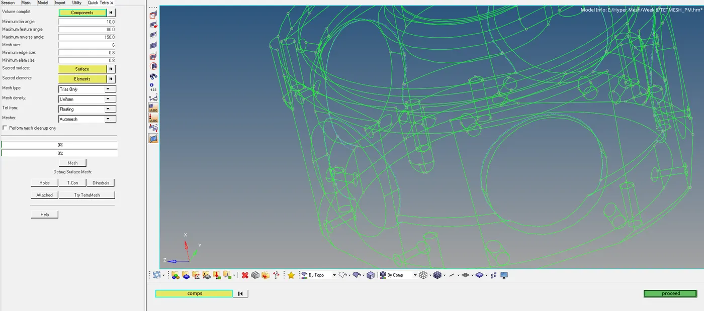
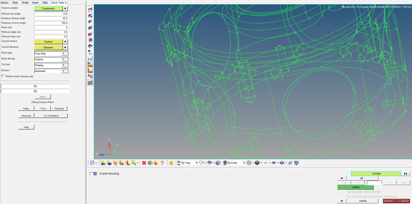
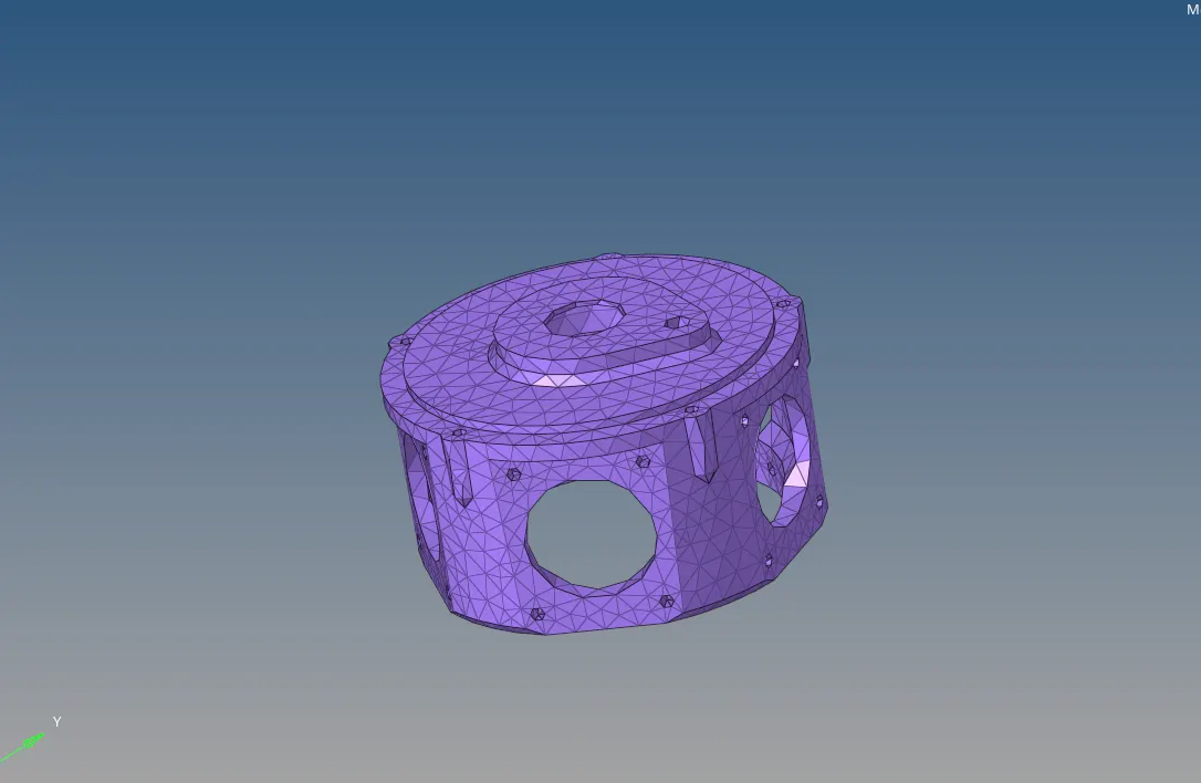
- The mesh is then created.
- Volume Mesh:
- Go to Volume Mesh Tab >> Select the Solid>> Uncheck use curvature,use proximity >> select 2D type as trias >> Give the Element size as “6” (given)>> Click on mesh.
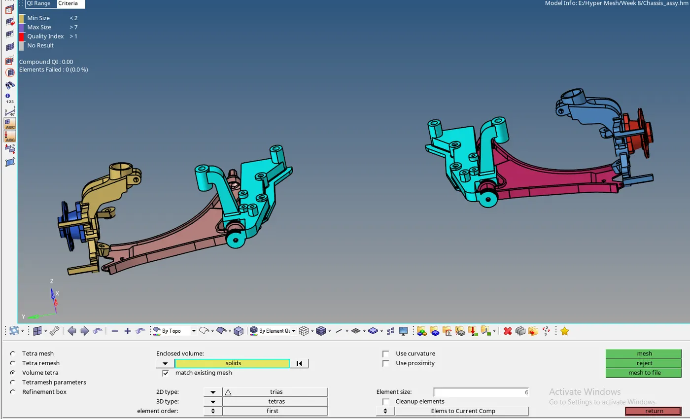

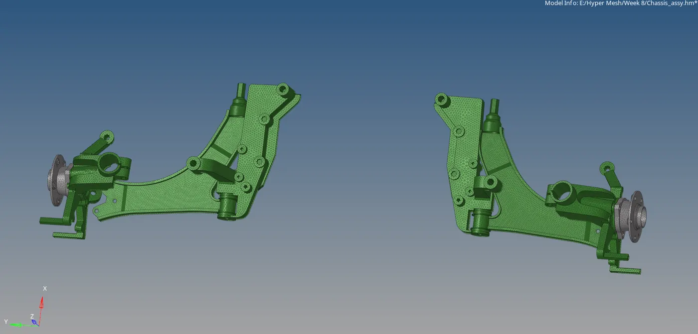
- The Volume is created.
- Reducing the Errors:
- For 2D errors:
- The 2D errors are cleaned easily in the Quality index tab. By using the Element optimize.
- Go to the 2D panel >> Click Quality Index>> Click on Cleanup tools >> select the tools to reduce the errors.
- For 3D tet Collapse:
- The 3D solids errors are mostly the Tet collapse. To clear them the translate option or to re-mesh the component.
- To find Tet Collapse, Click F10>> Go to 3D >> Select tet collapse >> the elements failed will be seen on the bottom left part.

- Go to the 3D Panel >> select the Tetra mesh >> Select Tetra remesh >> Select 3D elems >> change the Free boundary faces from fixed to remeshable >> Click remesh.

Tools Used:
The Tools used here are mostly from the Tetra mesh panel in the 3D Tab.
- Tetra Mesh:
- The tetra mesh meshes the component which is either 2D meshed elements to 3D or if the model is enclosed, the surface can be meshed directed.
- Tetra Remesh:
- The Tetra Remesh is used to clear the tet collapse and to make sure that the mesh is recreated with less or no errors.
- Volume tetra:
- The Volume Tetra is used to create the mesh for the Solids and surface (specifically with very less feature surfaces)
- Tetramesh Parameters:
- The Tetra Mesh parameters are used to give the component the parameter in which the component needs to be meshed. It helps to create an optimal mesh of the model.
Terms Used:
- Tetra mesh:
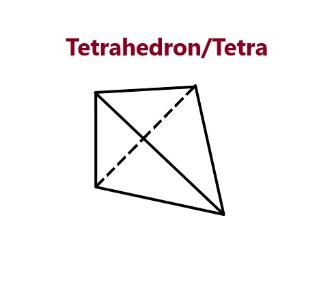
- Tetra mesh is nothing but the tetrahedron mesh. The Tetrahedron consists of 4 nodes which makes a 3 noded triangle and 1 node is created above the triangle at a certain height. When all the joined it forms a tetrahedron/ tetra element.
- These are used for the elements which have high thickness and complexity.
- Tet Collapse:
- The tet Collapse occurs when the elements fail to reach the optimum height for the given cross-section area.
- It is calculated by measuring the distance of a node from the opposite face, then the four values will be divided by the square root of the opposite face’s area.
- The minimum of four values is then divided by 1.24
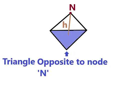
Tet collapse = `("Min of " (h/sqrtA))/1.24`
Where h is the height of the node and the opposite face of the Triangle.
A is the Area of Opposite Triangle.
Results:
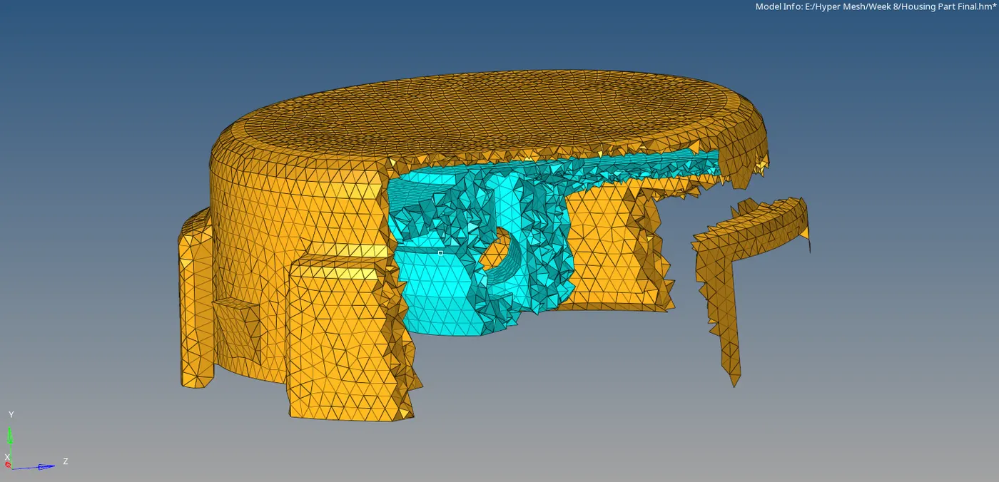
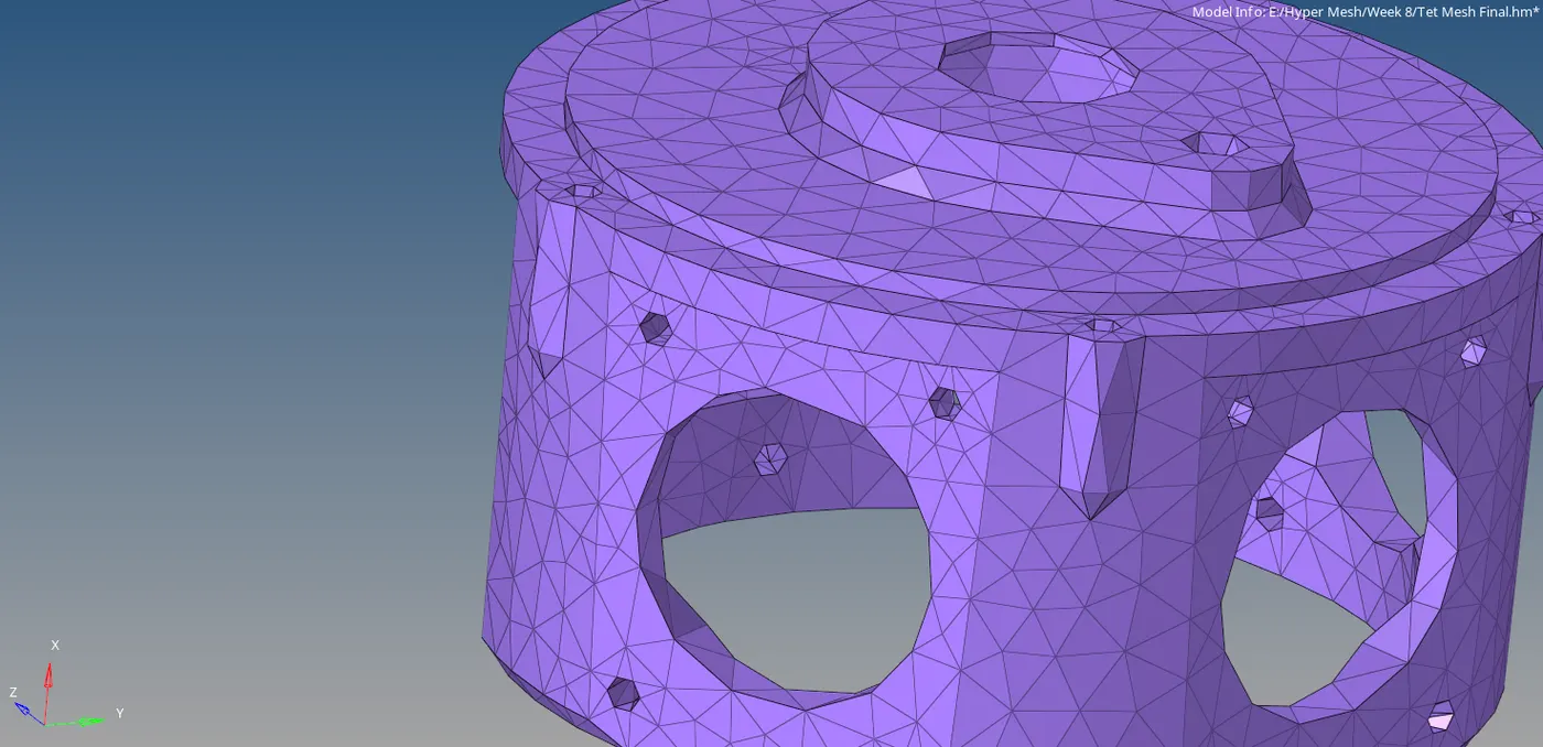
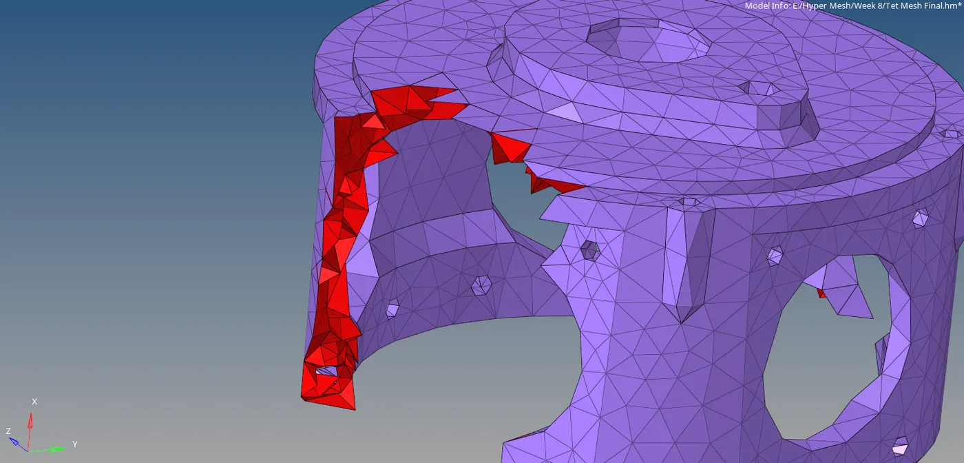
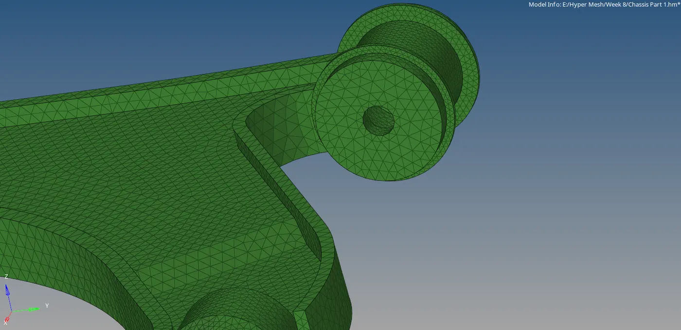
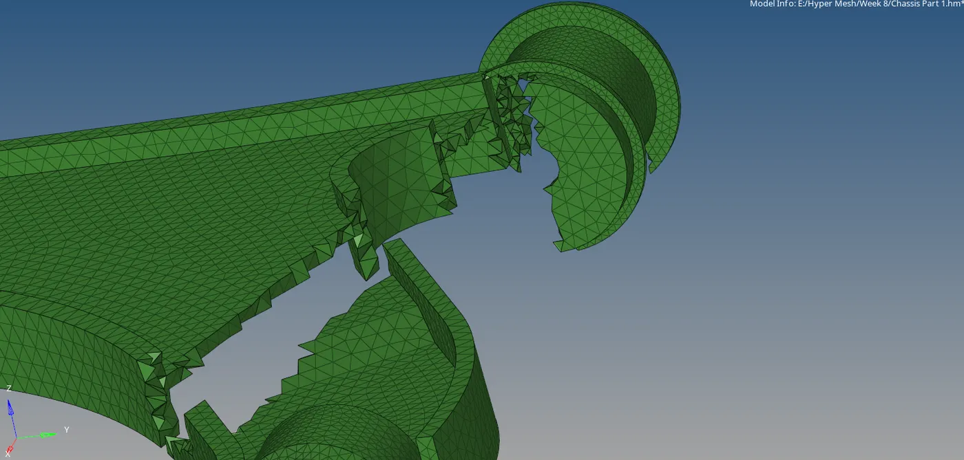
The Volumetric mesh is performed for the given models using different techniques.
For Model 1 (Housing):
For Model 2 (Crank Housing):
For Model 3 (Chassis assembly):
Errors Faced:
The Errors faced were due to the limited access of the student version of the software which can hold the elements limiting to 100000. and since the volume mesh for the third model has many components in it, the model isn't saving and showing the element count is above the limit and the model cannot be saved. To solve this, the model is exported the model into parts so that the component does come under the required limit.
Links:
The Data gathered for the tool is from google as well as some articles. The Link is provided below.
Google Drive link: Week 8 challenge