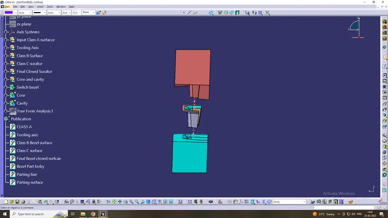
Week 8 - Challenge 6 - Core & Cavity Design
Creating the Tooling Axis
The tooling direction is used to find the direction in which the part is removed from the core and cavity. The draft angle should be positive to the tooling axis to manufacture the component easily. The step by step procedure of creating the tooling axis is given below.
Step: 1
Creating the point on surfaces respectively also extract the surface of the component
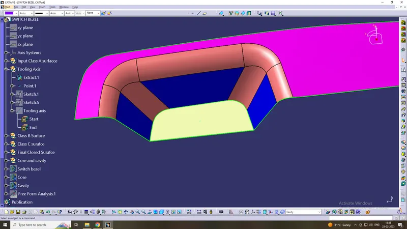
Step: 2
Now creating the intersection to the Z-Y and Z-X direction of the surface as shown below.
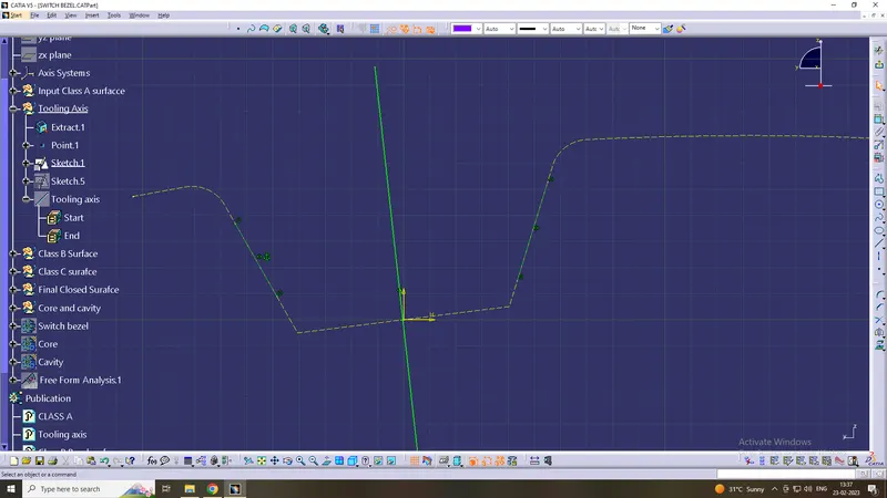
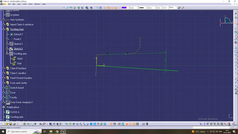
Step: 3
Now creating the bisecting lines for the intersection lines to the tooling axis for both Z-Y and Z-X axis. Once we get the bisecting lines for both axis now bisect that both bisecting lines to get min tooling axis.
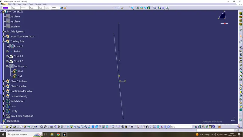
Finally we get our main tooling axis for the Switch Bezel component.
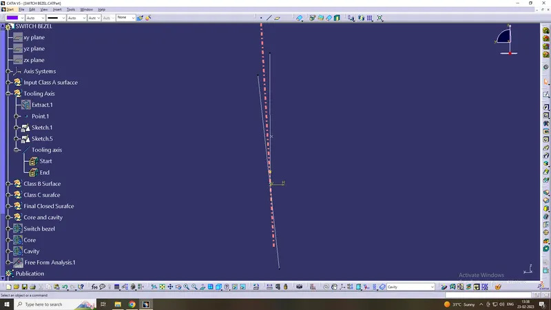
Draft Analysis
- Draft Analysis for Class A surface:
Step: 1
Initially we perform the draft analysis to the class a surface to ensure that we have good quality of surface to make Class B and C surface to achieve the same kind of quality surface. First we have to set the compass on the main tooling axis to get the direction of core and part moves along as shown below.
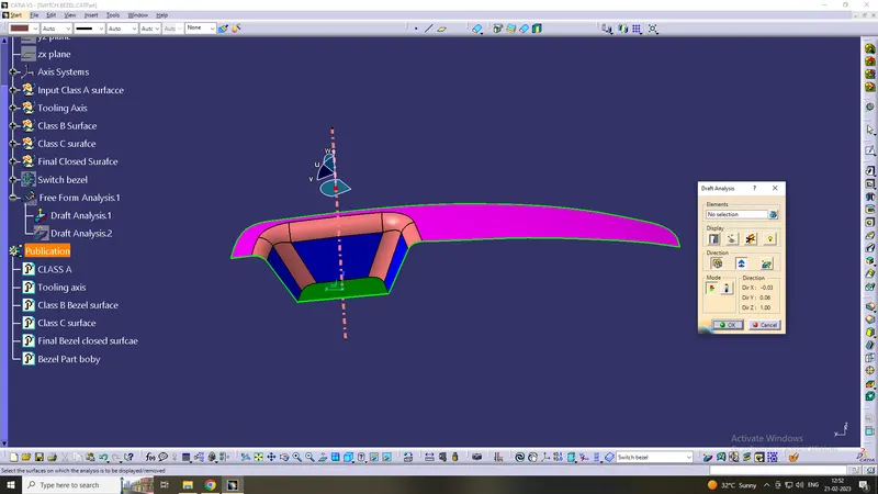
Step: 2
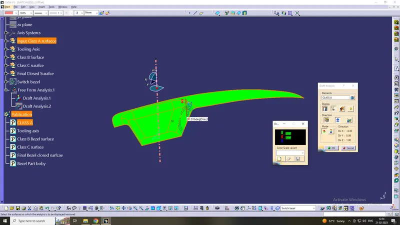
Once compass is locked in the axis, directly click on the surface it will appear quality of draft surface whether, it is pass or failed. Here the draft angle is given as 3 degree. Hence we achieved green colour on top surface. Hence it accepts the draft angle for the surface, so we build good quality component.
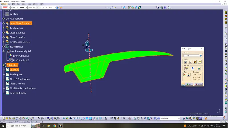
Step: 3
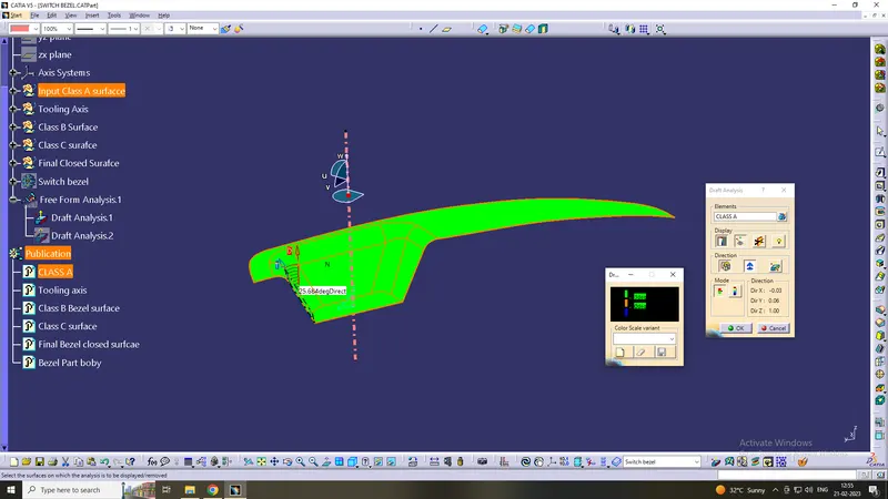
Now we check colour variant scale to ensure the maximum and minimum area draft angle is achieved by displaying by green, red and blue colour respectively. If the surface appears Blue in colour while analysing it is not accepted.
Step: 4
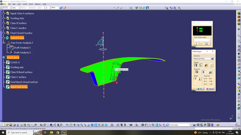
We can check the angle of draft given to surface by using draft tool analysis just point the over the surface where we have check angle of given draft to the component as shown below.
- Draft Analysis for final component:
Step: 1
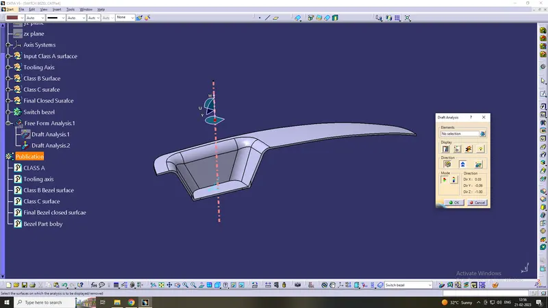
First we have to set the compass on the main tooling axis to get the direction of core and part moves along as shown below.
Step: 2
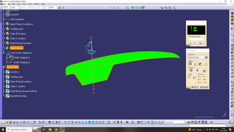
Once compass is locked in the axis, directly click on the surface it will appear quality of draft surface whether, it is pass or failed. Here the draft angle is given as 3 degree. Hence we achieved green colour on top surface. Hence it accepts the draft angle for the surface, so we build good quality component.
Step: 3
Now we check colour variant scale to ensure the maximum and minimum area draft angle is achieved by displaying by green, red and blue colour respectively. If the surface appears BLUE in colour while analysing it is not accepted.
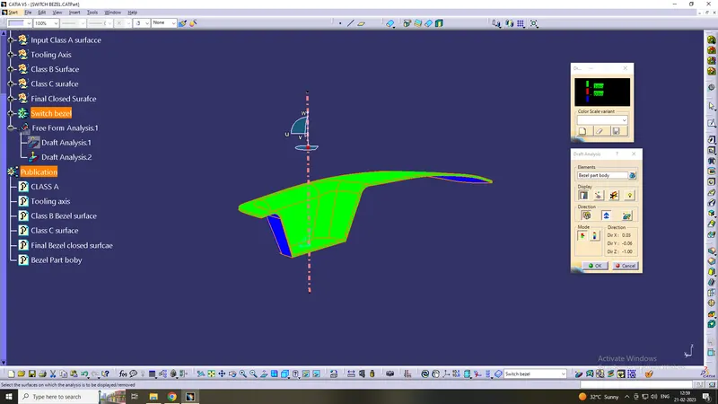
Step: 4
We can check the angle of draft given to surface by using draft tool analysis just point the over the surface where we have check angle of given draft to the component as shown below.
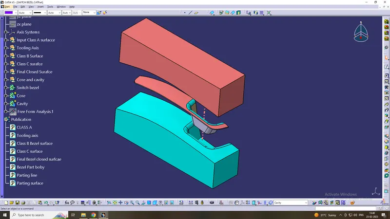
core and cavity blocks in various orientations
Isometric
Back view
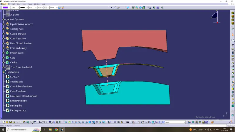
Right side