Week 8 - Challenge 6 - Core & Cavity Design
CORE AND CAVITY DESIGN
OBJECTIVE
Create Parting Surface and Parting Line for Switch Bezel.
Create Core And Cavity Blocks.
Show Draft Analysis Component with the Core and Cavity.
Make Solid a Body Using the Close Surface Feature from the surface.
Use Publications.
PARTING LINE
It is the line where the core and cavity intersect each other.
The parting line lies on the B surface of the Plastic component to protect the A surface from the splash.
PARTING SURFACE
The surface where the core and cavity meet each other is called the Parting surface.
The Parting surface also lies on the B surface side.
The below screenshot shows the surface in pink color which represents the Parting surface and the green line represents the parting line.
We can clearly see that the parting line and the parting surface are lying on the class B surface.
CORE AND CAVITY
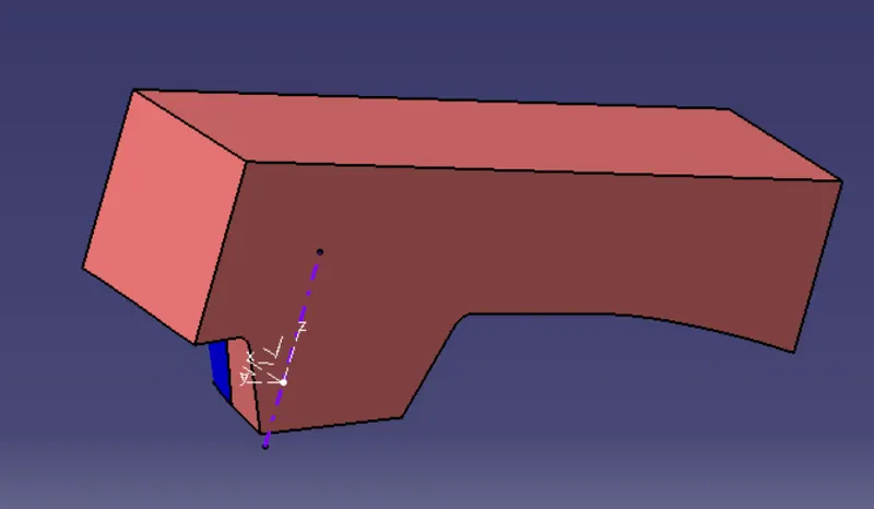
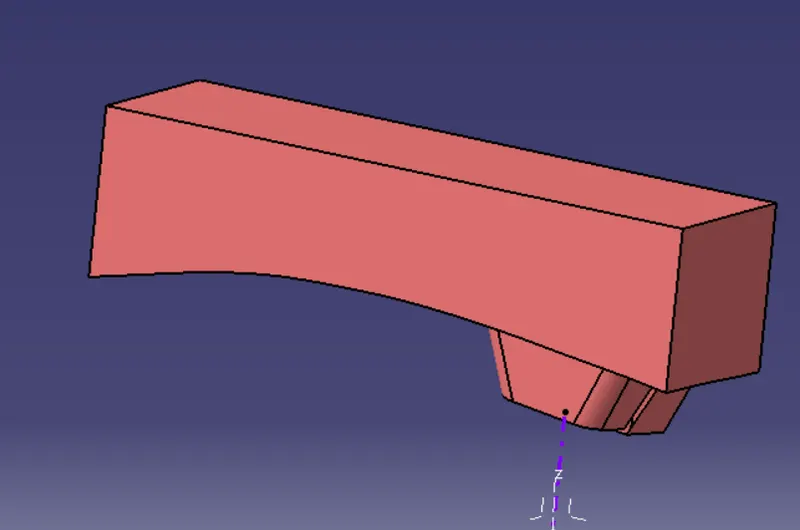
CORE
A movable side mold made the convex shape.
The mold closes the cavity and the core can make the geometry of the combined product.
The resulting space is called a cavity.
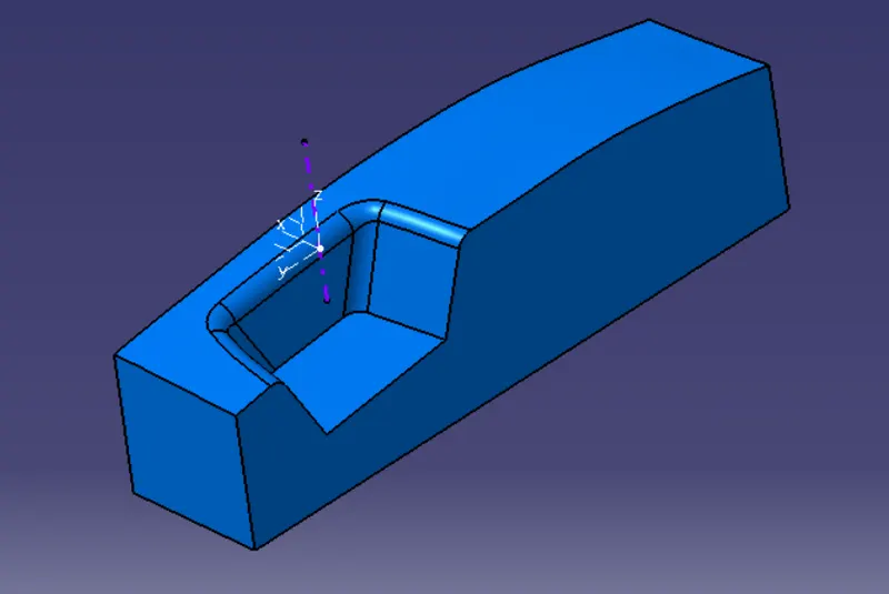
CAVITY
Molten plastic enters the fixed side mold and its made a concave shape.
Mold cavity referred to having the cavity mold tooling.
INTERSECTIONS
STEPS OF DESIGN
STEP-1
Open the existing Switch Bezel CATpart.
The below image is of Draft Analyzed Switch Bezel CATpart.
STEp-2
Show Class A Surface In that CATpart.
Perform boundary check on the Class A surface to ensure Class A is complete.
STEP-3
In this, we have to extrapolate the Class A surface for 15mm.
Then Trim it with Class C Surface.
STEP-4
A Parting Surface is a surface that separates the mold block into two parts – the core and the cavity. Usually Parting Surface is the biggest
projection outline of the part.
STEP 5
A parting line, in the industrial casting of molds, is the borderline in which draft angles change direction. That is, it is the dividing line that splits
the core and cavity halves of a molded part. It is sometimes a starting point for the mold parting surface.
CORE AND CAVITY DESIGN
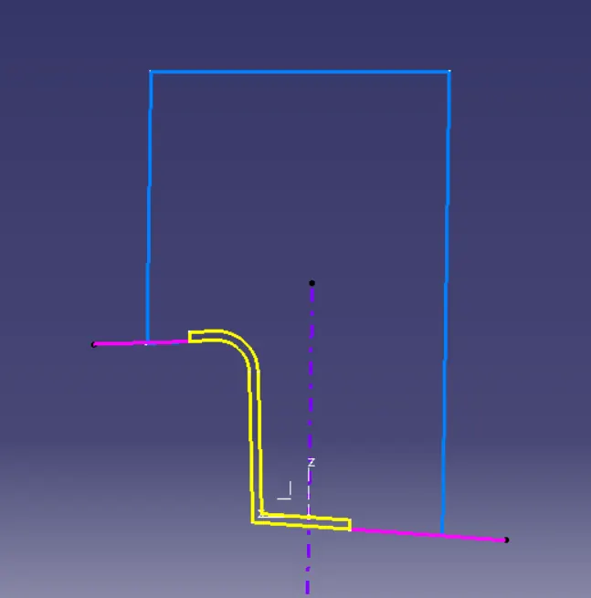
Start sketching for the core and cavity as shown below.
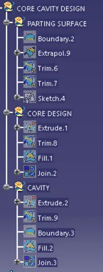
To fill the bottom half of the Core and Cavity first use Boundry Command to create a boundary.
Then use the Fill command with a boundary as a reference to fill the gap for both Core and Cavity.
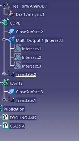
TREE STRUCTURE OF DESIGN
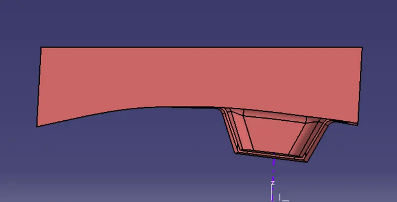
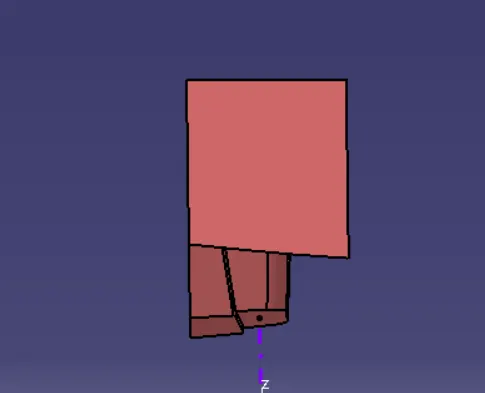
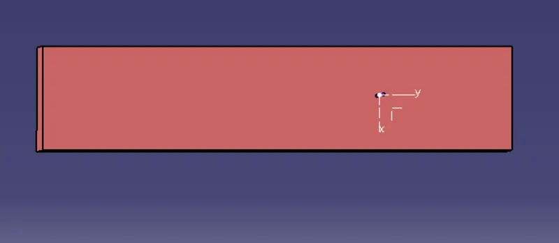
VIEWS OF CORE
ISOMETRIC VIEW
FRONT VIEW
SIDE VIEW
TOP VIEW
VIEWS OF CAVITY
ISOMETRIC VIEW
FRONT VIEW
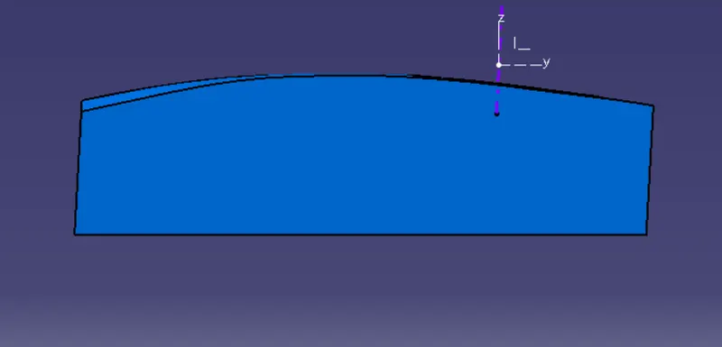
SIDE VIEW
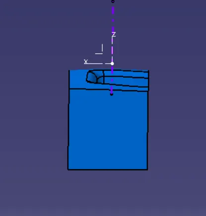
TOP VIEW
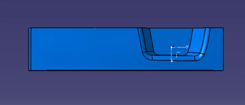
CORE AND CAVITY WITH TRANSLATION
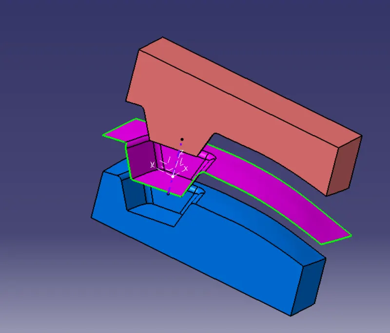
DRAFT ANALYSIS OF CORE AND CAVITY
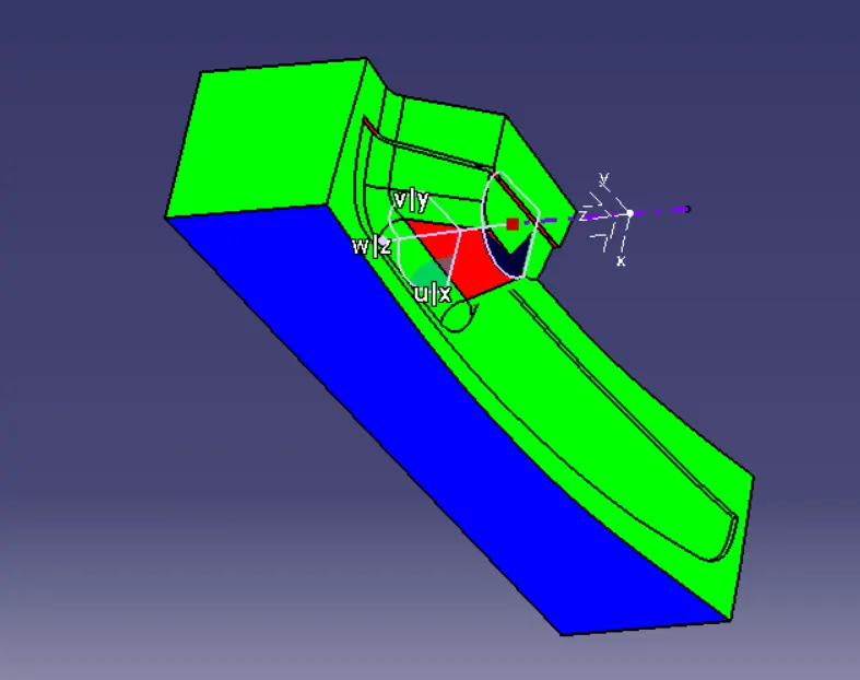
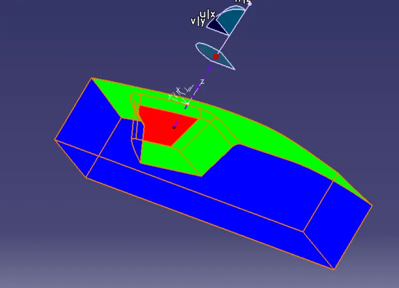
CONCLUSION
Create Parting Surface and Parting Line for Switch Bezel.
Create Core And Cavity Blocks.
Show Draft Analysis Component with the Core and Cavity.
Make Solid a Body Using the Close Surface Feature from the surface.THE ABOVE OJECTIVE IS COMPLETED