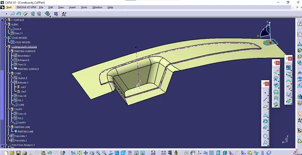
Week 8 - Challenge 6 - Core & Cavity Design
CORE & CAVITY DESIGN
CLASS A SURFACE
It is the surface which is given to the plastic designer as input.it is the outer most and aesthetic surface.
CLASS B SURFACE
A surface that is at a distance of thickness from class A surface is class B surface.all engineering features are contained in B surface.
CLASS C SURFACE
A surface that joints class A and class B is called C surface.
TOOLING AXIS
- First look at the part in all views and check which is the most appropriate direction for the tool axis.
- Then make a bisecting line between 2 inclined surfaces in the YZ plane.
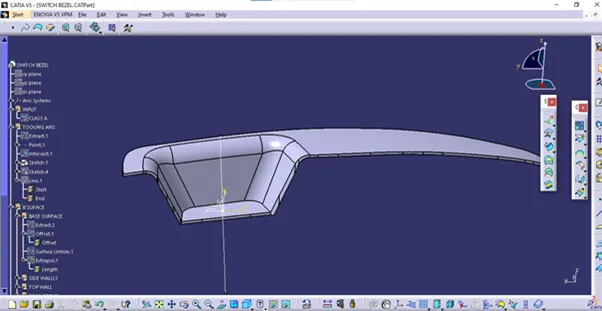
- Then project the inclined surface in the XZ plane.and draw a sample line parallel to that surface and make it more than 3 degree from the projected line by constraining it.
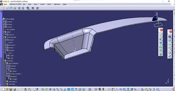
- Then draw a bisecting line between these 2 lines which is the final tooling axis.
DRAFT ANALYSIS
- Draft analysis is done to check whether the part designed is manufacturable or not.
- Minimum draft angle considered is 3*.
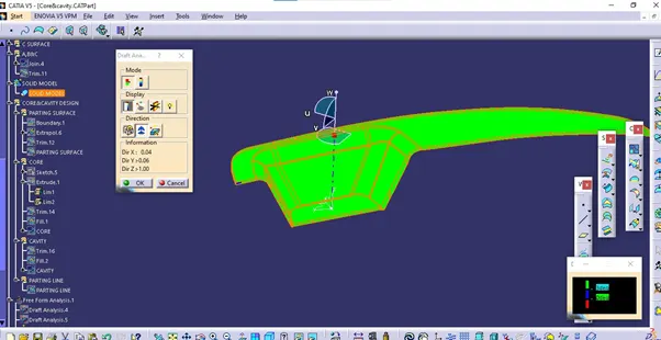
- For analysis goto insert>analysis>feature draft analysis.then place the compass on the tooling axis and click on the part.
DRAFT ANALYSYS ON CLASS A SURFACE
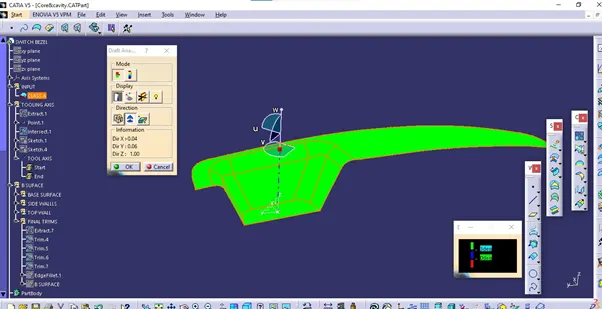
DRAFT ANALYSYS ON FINAL SURFACE
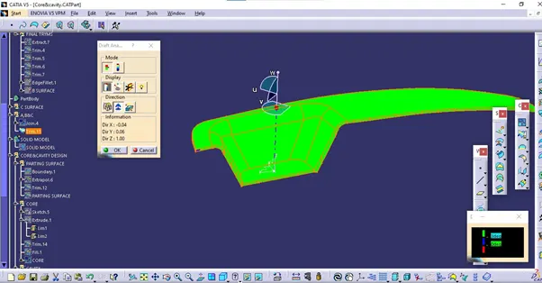
DRAFT ANALYSYS ON SOLID MODEL
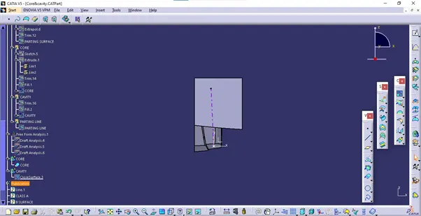
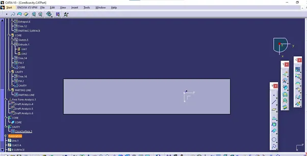
CORE
- it is a profile or pin which is used in Mould to create a Hollow / Holes in castings.
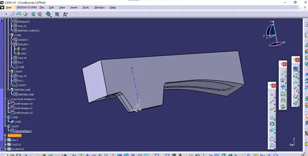
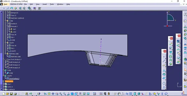
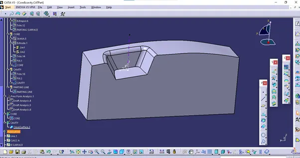
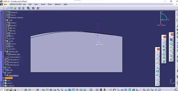
CAVITY
- It is the area in the mould which is filled with molten metal.
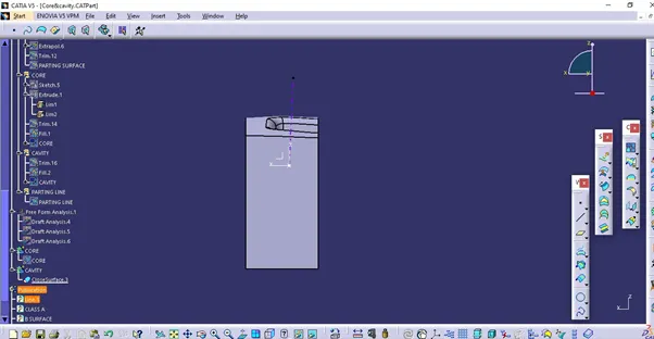
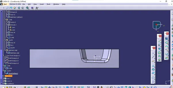
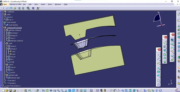
PARTING SURFACE AND PARTING LINE
- Parting surface is known as the surface of contact within any two segments of the mold.
- Parting line is the line where parting surface meets with the casting surface of the mold.