Week 8 - Challenge 6 - Core & Cavity Design
CORE AND CAVITY DESIGN OF A SWITCH BEZEL:-
AIM:To Create the Switch Bezel Plastic component through the given Class A surface. To begin with, the tooling axis for the given Class A Surface should be created meeting the requirements of the draft angle and also Create the Class B Surface & Class C Surface. At the end perform to give thickness of the model and also to create the Core and cavity blocks for the switch bezel designed in the earlier.
DRAFT ANALYSIS
- Draft analysis is performed based on color ranges identifying zones on the analyzed element where the deviation from the draft direction at any point, corresponds to specified values. Draft is required on all parts in the direction of mold movement in order to allow parts to release or eject from the properly.
- Draft is the angle in which the parts is tapered to allow it to release. As the part cools, it tends to want to shrink to the core side of the mold. The draft allows the parts to release easily from the mold without creating friction between the surface of component and the core and cavity plates.
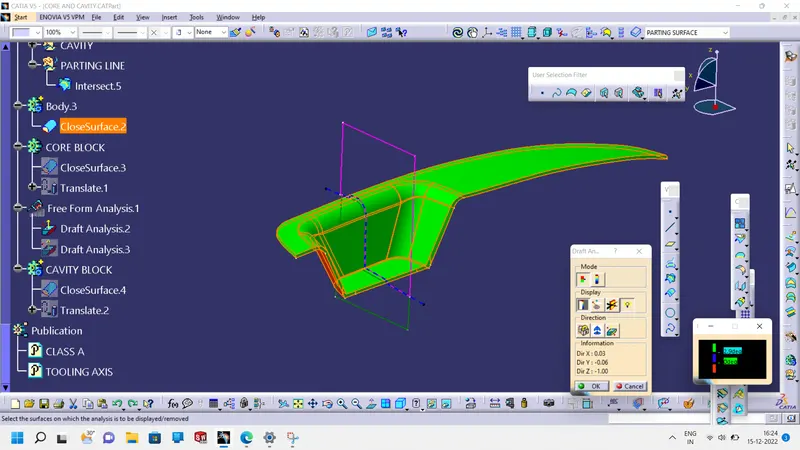
TOOLING AXIS:
- It is the direction in which the mold open or core & cavity open. Part drafts are given along this axis.
Tooling operation:
- To decide the tooling axis, the component should be completely clearing the Tooling axis in the given specific direction. Analysis the components, the fan cover components has two walls.
- First one visually check. We can check, which one is possible to Tooling Direction. We can check al x, y & z direction. If you have hole, what it will happen, you haven separate side core for specific hole. In this draft analysis of fan cover Z – direction is the possible of tooling direction.
CORE AND CAVITY DESIGN:
- The mold core & cavity are the shaped sections in either half of the mold tool which give the plastic product its final shape.
- The hot molten material is injection into the core & cavity and then sets hard into shape. The design of the core & cavity is essential in the correct formation of the product. The sequence of events during the injection mold of a plastic part is called the injection molding cycle.
- The cycle begins when the mold closes, followed by the injection of the polymer into the mold cavity.
- A core is usually made of the best quality sand and is placed into the desired position in the mold cavity. Core prints are added to both sides of the pattern to create impressions that allow the core to be supported and held at both ends.
Parting Surface:
- The parting surface of a mold are those surface of both mold plates adjacent to the impressions which butt together to form a seal and prevent the loss of plastic material from the impression.
- Create the boundary line from Class A surface and Extrapolate it.
- Trim the both command Extrapolate and Trim. from under Class B surface.
- Trim the Class B surface and previous trim.11 command, to get parting surface of core and cavity design.
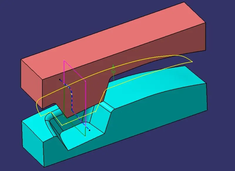
- The below figure is known as Parting Surface of the core and cavity design.
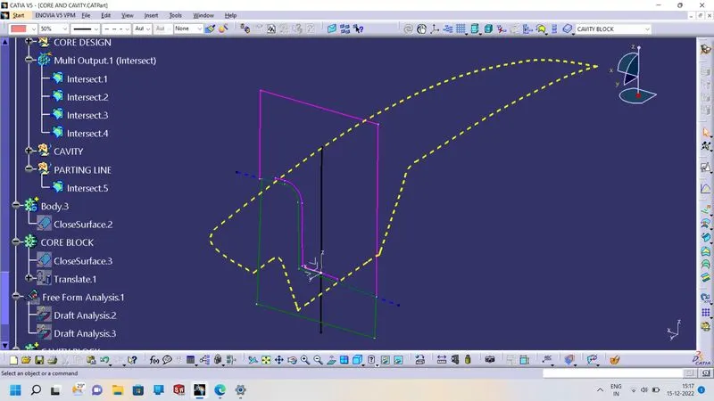
- To intersect the Axis System of ZX plane and select the cavity surface model, to get sketch profile.
Core Design:
- The core design is started extracting the parting surface that becomes the datum for the core and cavity. The parting surface in most of the cases is kept at the b Class surface to avoid close and tight contact between the core and cavity.
- Draw Rectangular profile on Axis system XY plane.
- Extrude the profile along Z direction.
- Trim the surface of parting surface with component area and Extrude.
- Fill the top of the surface area.
- To join the Fill surface and Trim Surface to get Core Design surface model.
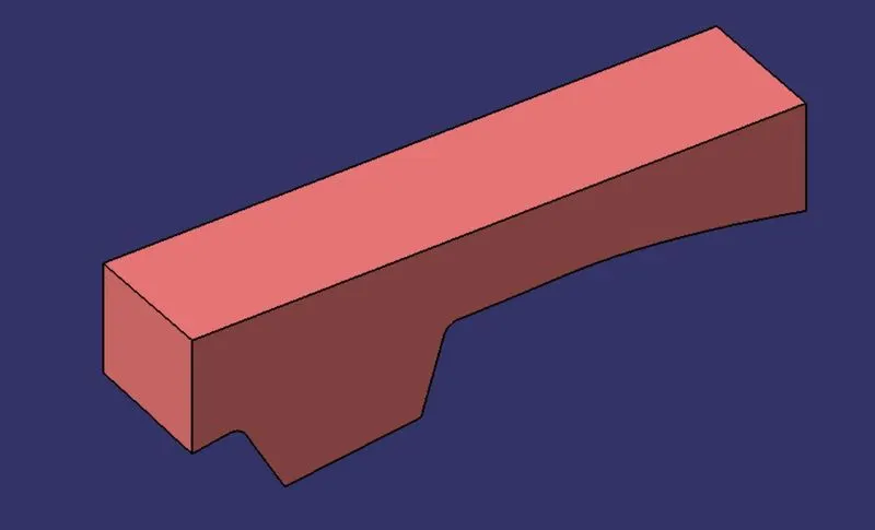
- To intersect the Axis System of ZX plane and select the core surface model, to get sketch profile.
Cavity Design:
- The cavity is the part where the injector and filling of the molten plastic happens. The cavity block is prepared by first extruding the outer boundary along the tooling direction.
- Draw Rectangular profile on Axis system XY plane.
- Extrude the profile along Z direction.
- Trim the surface of Class B surface and extrude.
- Fill the top of the surface area.
- To join the Fill surface and Trim Surface to get Cavity Design surface model.
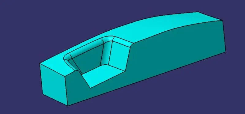
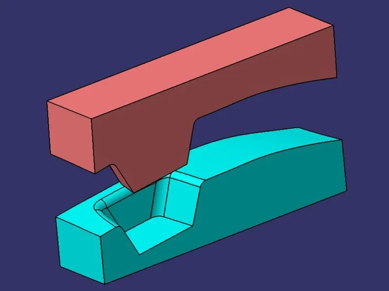
CORE AND CAVITY .
METHODOLOGY:
In this model we have focused on the following things:
Tooling axis
Draft analysis
Class-B surface
Class-C surface
Making a solid model from surface.
Following tools were used to reach the final step:
Extract
Un-trim
Trim
Extrapolate
Offset
Edge fillet
Boundary
Sweep
Join
Close (part design)&Translate.
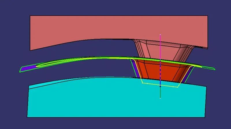
FRONT VIEW
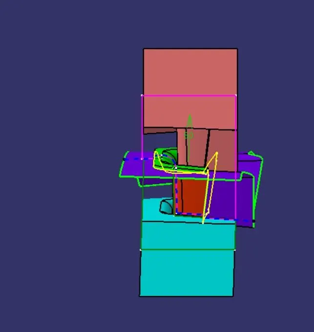
LIFT SIAD VIEW
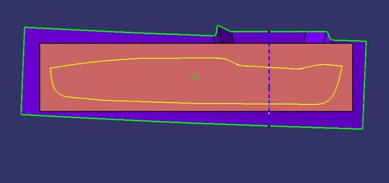
TOP VIEW
ISOMEYRIC VIEW
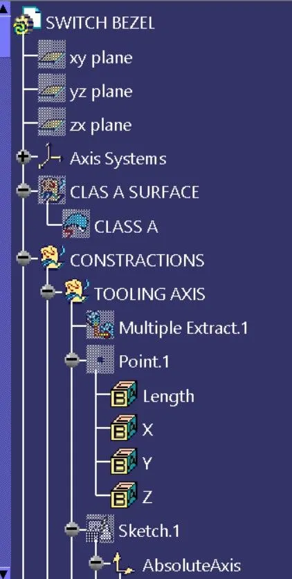
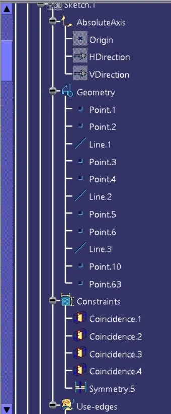
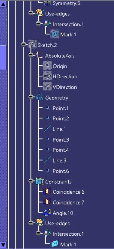
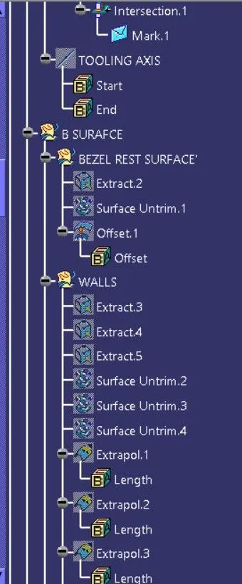
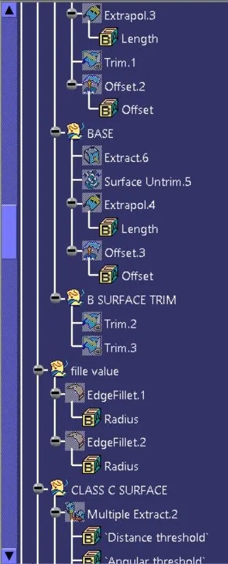
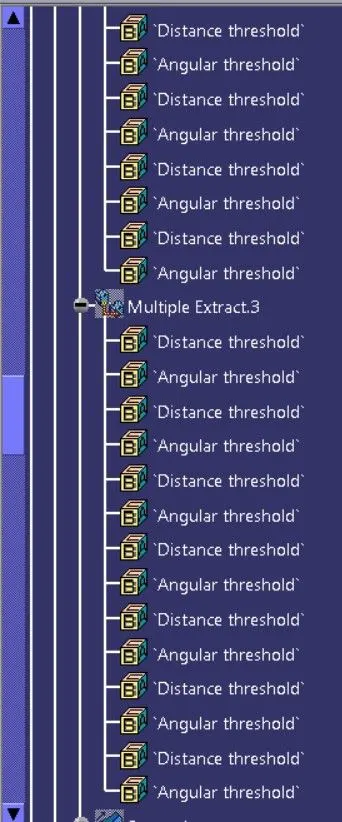
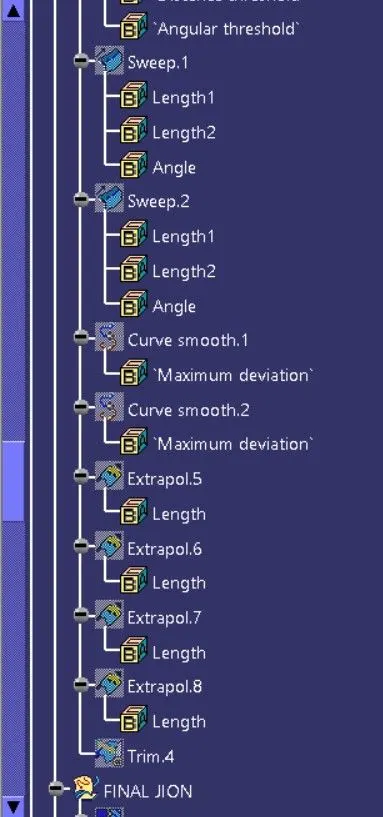
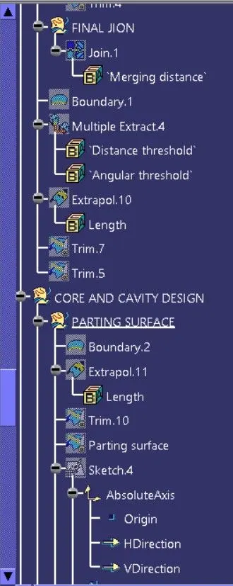
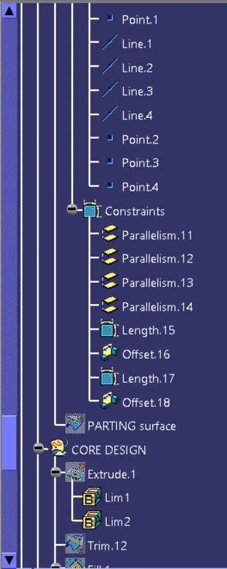
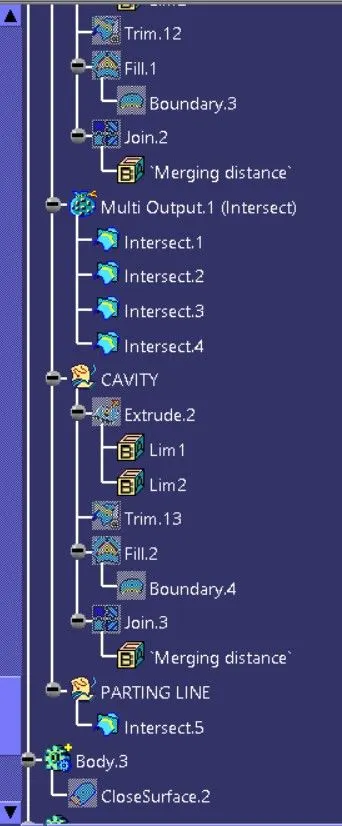
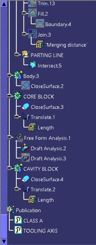
ENTIRE TREE STRACTURE
CONCLUSION :
- The creation of Core, Cavity, Parting line and Parting surface were done.
- The Drafting analysis was performed.
- The solid component was created from the surface geometry.
- The Translation of Core and Cavity block was done inorder to observe their operation along Tooling axis,
- The necessary screenshots and files were attached.