Week 8 - Challenge 6 - Core & Cavity Design
CORE & CAVITY DESIGN REPORT
AIM
- To Create Core, Cavity, Parting line and parting surface for the Switch Bezel Component along the Tooling Axis.
INTRODUCTION
Core
- A Parting surface is a surface in the model that you designate to split a workpiece, die block, or another volume.
- A Parting line is the line of separation on the plastic part where the two halves of the plastic injection mold meet.
DESIGN METHODOLOGY
Tooling Axis Creation
The tooling axis is the direction of drawing a sheet metal where the finished component is easily ejected on a particular direction and axis.
In Molding, machine arrangement is given to open the mould along a direction which is known as Tooling Direction. In other words. The mould is built from two separate halves (Core and Cavity) and tooling direction basically defines the direction of mould pulls apart.
There are 3 methods to create tooling axis, which are :
- With respect to 3 axis (X, Y, & Z)
- Normal to surface
- Bisecting method
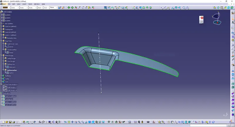
In the given model tooling axis is found out using Normal to Surface method.
In the given model (switch bezel), it will clear all the surfaces in its Z-axis direction, so that the surface approximately perpendicular to z-axis is chosen and is extracted from the class A surface. Tooling axis is drawn normal to that extracted surface.
Tooling Axis:
Cavity Creation
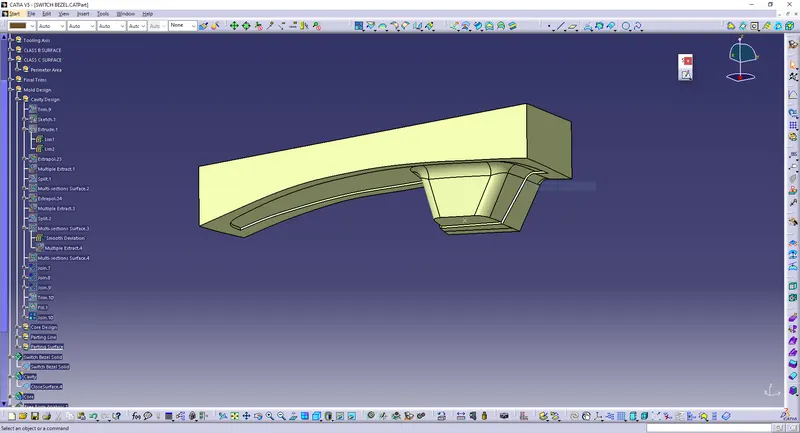
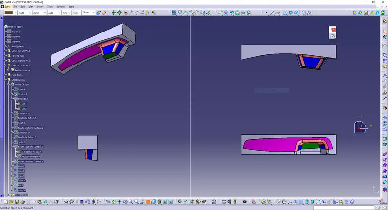
The Rectangular extrude was used to create the cavity as well. This extrude was Trimmed with the Class B to form the Cavity part. The Cavity was closed at the top using Fill command and was further joined using Join command.
Created Cavity in closed surface:
Screenshots of the cavity solid body in various orientations:
Core Creation
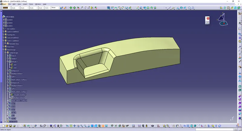
A Rectangular shape was formed and extruded along the tooling axis such that it stays inside the region of the Parting surface.
This extrude was Trimmed with the Parting surface with component to form the Core part. The Core was closed at the top using Fill command and was further joined using Join command.
Created Core in closed surface:
Screenshots of the core solid body in various orientations:
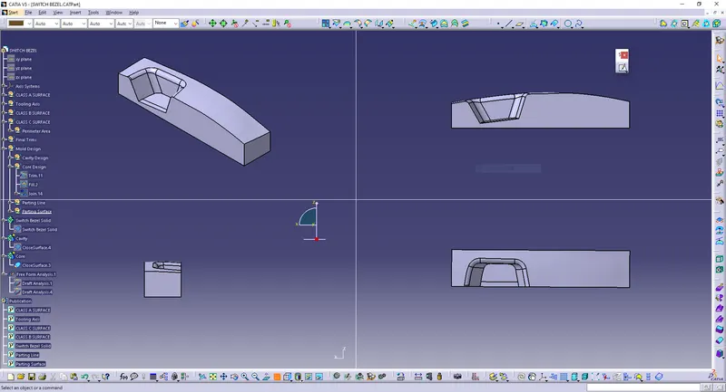
Draft Analysis Report
Cavity & Core
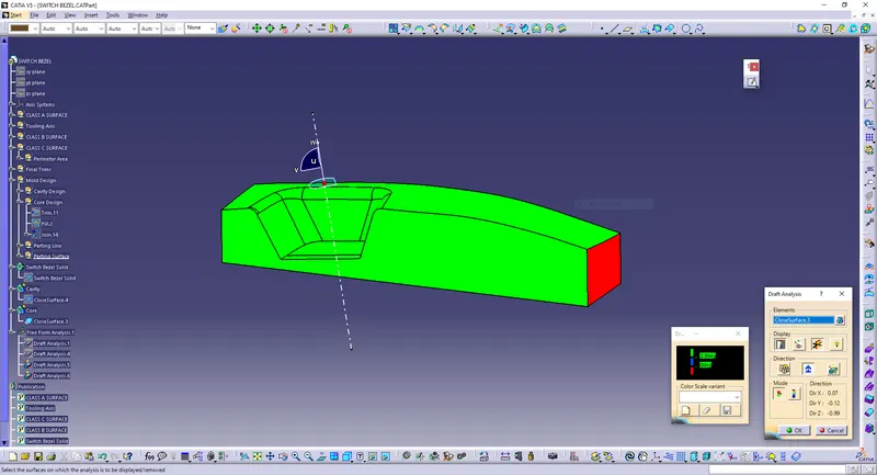
In the criteria of making a plastic material, the mold should release the material when finished. If the mold surfaces are 90 degrees the material won't release from the mold because of friction due to contraction of material when cooled.The ejection of the part from mold depends on the draft. A zero draft can result in difficult or no ejection. It is recommended to add a draft of 3 degree or above inorder to remove it from the mold without any damage.
Procedure:
- Change the view mode of the component to be in customized parameter mode and then select the shading mode as materials.
- In the draft analysis toolbar, set the draft values and color (3 degree and above as green, 0 to 3 degree as blue, less than 0 as red).
- Drag and drop the axis system on the tooling axis and lock it.
- Perform draft analysis.
Draft analysis of Cavity:
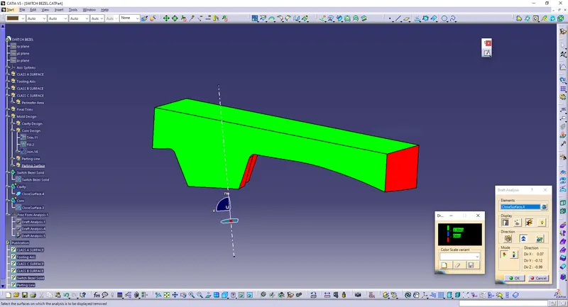
Draft analysis of Core:
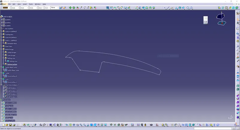
Parting Line
Initially the Class A surface was Extrapolated. It was then Trimmed with the Class C surface.
This output was further trimmed with Class B surface along with the component. The Parting line was created as an Intersect with Class B with a Trimmed surface.
Parting Surface
Mold has two major components one is core and another is cavity .during the injecction molding process, these two halves are pressed tightly from a sealed hollow to avoid the melt flow leakage and maintain certain holding pressure, the pressed surface are called parting surface , usually parting surface are the biggest projection outline of the part.
The Parting surface was obtained by Splitting the Parting surface with component with the Parting line.
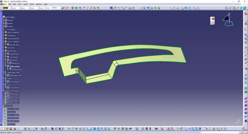
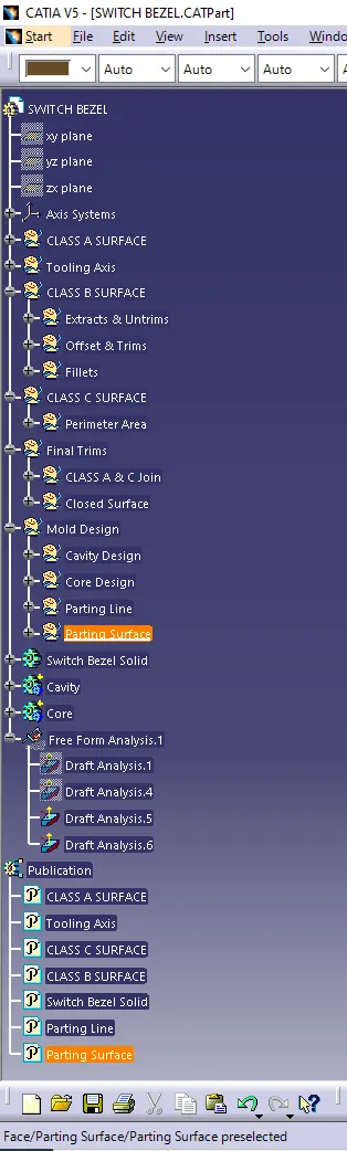
Tree:
CONCLUSION
Designed the Core and cavity blocks for the switch bezel and done the dratt analysis successfully.