Week 8 - Challenge 6 - Core & Cavity Design
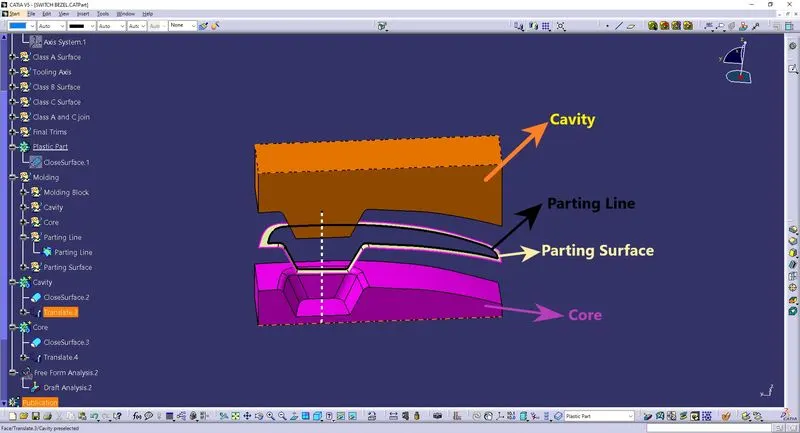
Objective: To design a core and cavity for the given plastic and also to show its tooling axis, drafting analysis, parting line and parting surface.
Tooling Axis:
When a plastic body is created in a molding, the cavity and the core is moved respectively to one another. The plastic component is poured and ejected respectively to that axis of the core and cavity motion. This axis is called as "tooling axis". For the challenge to be satisfied, the discussed tooling axis must be created for the product, keeping the motion of core and cavity in mind.
Steps in Catia to add tooling axis:
- An visual analysis by us to be undertaken at every axis plane of X,Y and Z to come up with the suitable plane that holds all the features of the surface A.
- Here the Y and X axis, doesn't suit the above requirement, hence moving to X-plane we preserve majority of the details given to surface A.
- At first we must create a geometrical set, where it should be renamed as the "Tooling axis".
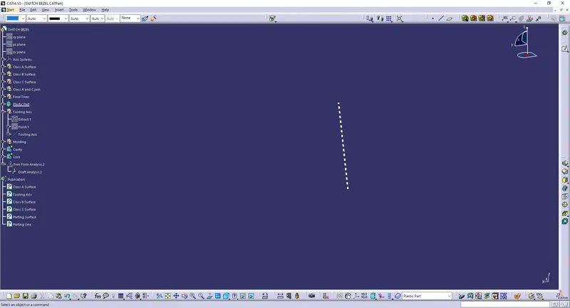
- To Fix X axis as the tooling axis, we must construct line to represent it.
- For the line creation, we can use the hole present in surface A as the reference and using the point option, we must include a point in the centre of the hole.
- Now to draw a line, use the line-direction command, where the previously created point as the starting end, we must extend it on both the sides for a considerable distance, with X-axis as the direction.
- Now to comfortably view the final tool axis, we must publish it separately using publish command in the tools option in CATIA.
Tooling Axis snippet:
Draft Analysis:
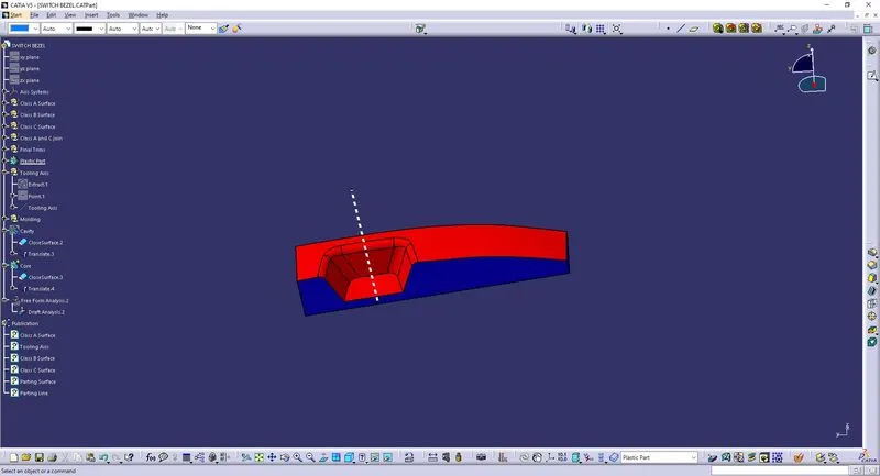
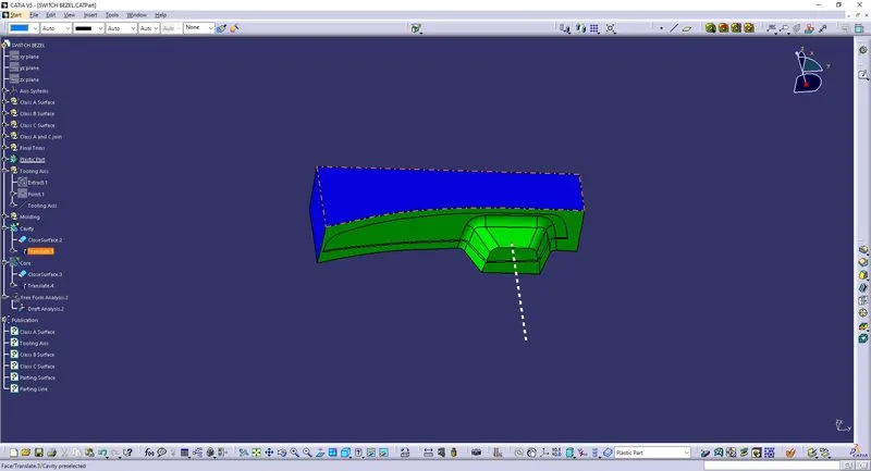
The drafting analysis done to ensure the draft angle given to the surface C is within the standard range of 3 degree. By keeping this angle, the part produced are safer to be ejected by the ejector pins, without being damaged. The color order of GBR (i.e., Green, Blue, Red) discusses whether the draft angle is safer in limits,
- if it is green, then the draft is within 3 degree
- if it is blue, then the draft is not less than 0 and not more than 3 degree.
- if it is red, then the draft is less than 0.
Here in the core and cavity design, the draft analysis is done to make sure the core and cavity's surface impression and projection are relative to the draft clearance of the Class A and Class B Surface. So the color coding will be respective to the surfaces' color in the final trim/closed body of the final trim.
Steps in Catia to Drafting Analysis:
- Add material using the view option to let the draft analysis to run.
- Select the surface or final part body to make it highlighted in the feature tree.
- Use the analysis in the insert option in the CATIA's menu bar, to find the Feature draft analysis.
- Now after selecting the option, two pop window will be displayed, where:
- One has the colour coding, where we must define the colors in the order of GBR (Green, Blue, Red) respectively and set the angle value to be 2.9 for Green, 0 for Blue, and less than 0 as Red.
- Other pop up has several tools for draft analysis, Now from the right most corner of the screen, drag the direction compass and place it on the tooling axis, where the resulting compass aligns with the tooling axis. Now after it gets aligns, lock the compass position using Compass Lock tool.
- To view the draft analysis, select the Surface or final closed body. By choosing it as mentioned, the analysis produces the color coding over the parts where the draft condition/angle satisfies as we mentioned.
Draft Analysis snippet:
1. Core
2. Cavity
Parting Line and Surface placement:
- For every plastic model of its draft definition, the Parting Line decides the Class C Surface's position with either Class A or Class B surface.
- To choose the ideal parting line, we must approach the plastic component by viewing its orientation parallel to the tooling axis and viewing it from Class A Surface.
- Here, the draft is given outwards and the draft can be seen along with the Class A Surface.
- So, it's comes under the Case 1 where the parting line must separate Class A and C in cavity and Class B in core.
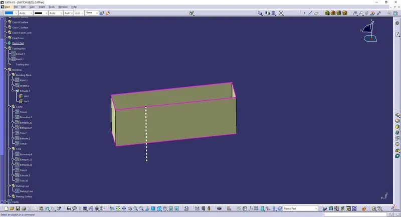
Mold: Mold is the combined part of the Core and Cavity and have its own dimensions with respect to the molding process.
Steps to create the mold:
- Introduce a new axis system into the Catia, using axis systems.
- Now create a point at 0,0,0 coordinates.
- Use the projection point as the reference create a rectangular sketch, covering the final trim portion excessively.
- Extrude this trim covering the Final trim.
Mold Snippet:
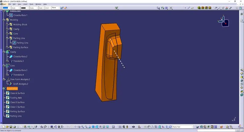
Cavity: Cavity is the stationary part of the mold where the injector injects plastic into the cavity when the core gets locked with the cavity. It holds the Class A Surface of the mold.
Steps to create the Cavity:
- Get the created “Class A and C Join Surface” and “Class B Surface”, use the trim option to get the exterior part of both AC join and B surface.
- Extrapolate the trim in such a way, it intersects the mold on all four sides.
- Now use this extrapolated trim and trim the upper part of the Mold Surface which has been created early.
- Now cover the open surface of the top, using the fill option.
- Now use closed surface in part design to make solid out of it.
- Thus the Cavity is created.
Cavity Snippet:
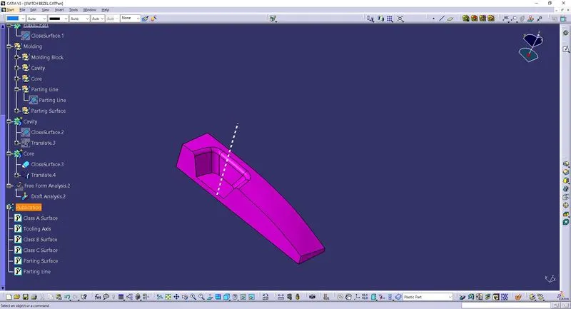
Core: Core is the moving part of the mold and the part where ejector pins lies. The core engages during injection and retracted during the ejection. It holds the Class B Surface of the mold.
Steps to create the Core:
- Get the created “Class B Surface” and Mold Extrude, use the trim option to trim the lower portion of the mold with interior surface of B.
- Extrapolate the trim in such a way, it intersects the mold on all four sides.
- Now cover the open surface of the top, using the fill option.
- Now used closed surface from Part Design to make solid out of it.
- Thus the Core is created.
Core Snippet:
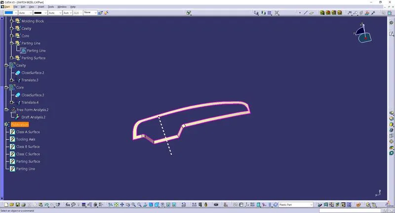
Parting Surface:
When the Cavity and the Core meets during the Injection Process or when it's about to start the Ejection process, the area where the cavity rests over the core is called the Parting Surface.
Steps to create the Parting Surface:
- Use the Class A and C join surface and Class B Surface, to get the intersection of the both.
- Now use the spilt on Class B Surface, using the intersection as the cutting element.
- Save it in a different Geomentrical set.
- Parting Surface is created and save it in a geomentrical set.
Parting Surface Snippet:
Parting Line:
The Line that falls on the intersection of Core and Cavity, where the plastic is sealed inside the mold by the locking of core and cavity is called Parting Line.
Steps to create the Parting line:
Now change the name of the intersection geometrical set as Parting line.
Parting Line Snippet:
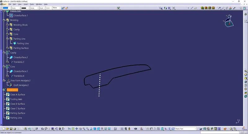
Feature tree snippet:

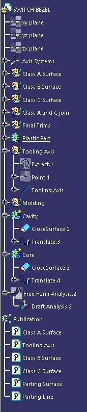
Combined Look Snippet: