Week 8 - Challenge 6 - Core & Cavity Design
Core & Cavity Design
Aim:
Create the Core and cavity blocks for the switch bezel designed in the earlier challenge.
Steps Followed:
- Tooling Axis creation
- Checking Draft analysis for created tooling Axis
- Creating parting Surface
- Creating Core Side
- Creating cavity side.
INTRODUCTION:
- The control panel bezel is the frame part of the window switch that holds its switch covers and buttons into place.
- Moulding is the method used to manufacture the plastic trims of an automotive by most OEM’s, hence by considering the manufacturing consideration the switch bezel is designed.
CLASS-A SURFACE: the class-A surface is used in the automotive design industry. it the describes the final production surface data for the aesthetic parts of the car.
CLASS-B SURFACE: The Class B finish is a quality finish with only minimal imperfections.
CLASS-C SURFACE: The interior surfaces not readily visible, surfaces that will be covered by another part when assembled, or surfaces which the Customer feels do not need to meet a high cosmetic finish.
Creating tooling axis:
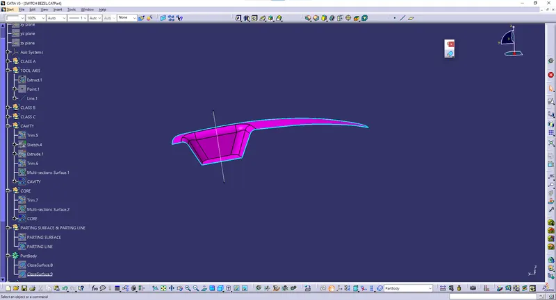
- The ejection from the mold after manufacturing the interior trim must have the nominal 3-degree draft angle.
- hence the tooling directions created by considering the above factor and bisecting method is used.
- The base surface of the class-A was extracted to create a reference point on the surface using the point, create a line in the z-direction and an axis system was inserted to the point
- Tooling direction is the main consideration for plastic part and mould parts because it defines the movement of the mould part and the possibility of the plastic part coming out from the mould part (Core and Cavity).
DRAFTING ANALYSIS:
- Draft analysis is performed on the components where the ejection of materials happens after the material is made inside the tools.
- In the case of automotive sheet design manufacturing, the blank sheet after turning into automotive panels like Hood, Fender, Roof, Side Doors, Back Doors etc. need to be removed from Panel Dies.
- If a considerable amount of draft angle is not provided, the removal of components from the tool will be difficult.
- It’s the same in the case of mold(plastic component) after getting filled inside the core and cavity, it needs to get ejected easily with the help of ejectors.
CORE :
- Core is a preformed, bonded, sand insert placed into the mold to shape the interior of a casting or a part of the casting that cannot be shaped by the pattern.
- Core is the male part which forms the internal shape of molding.
- Cores are often used to create hollow sections or cavities in a casting.
CAVITY :
- Cavity is the combined open area of the molding material and core, where the metal is poured to produce the casting.
- The cavity is the female part which forms external shape of molding.
PARTING SURFACE & PARTING LINE :
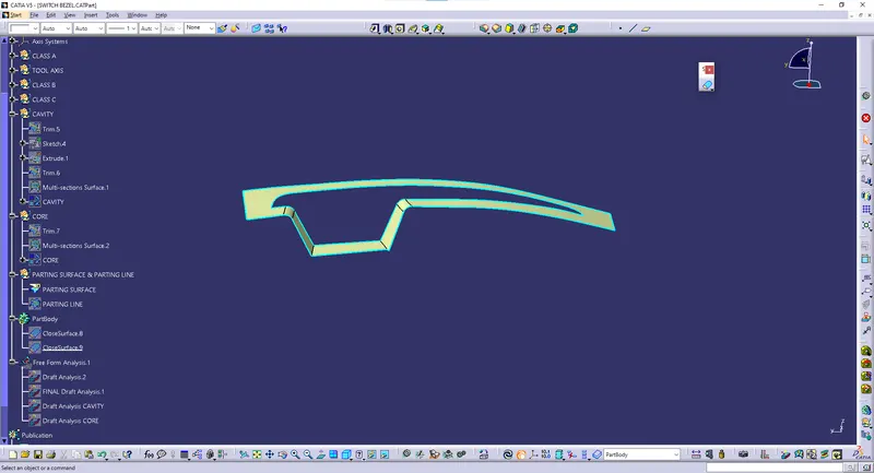
- A Parting surface is a surface in the model that you designate to split a workpiece, die block, or another volume.
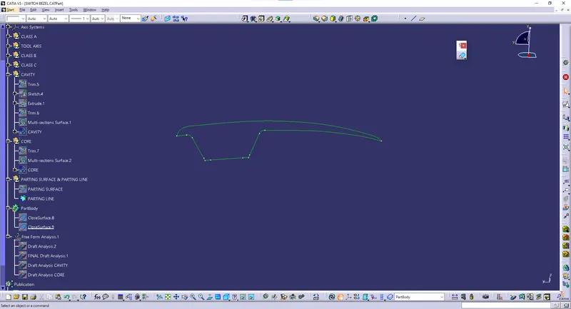
- A Parting line is the line of separation on the plastic part where the two halves of the plastic injection mold meet.
Creating Parting surface & Parting line:
- Initially the Class A surface was Extrapolated.
- It was then Trimmed with the Class C surface.
- This output was further trimmed with Class B surface along with the component.
- The Parting line was created as an Intersect with Class B with a Trimmed surface.
- The Parting surface was obtained by Splitting the Parting surface with component with the Parting line.
PARTING SURFACE:
PARTING LINE:
Creating Core:
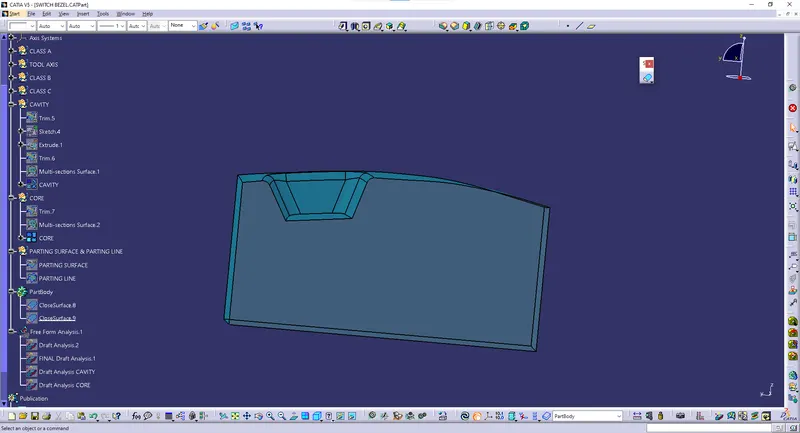
- A Rectangular shape was formed and extruded along the tooling axis such that it stays inside the region of the Parting surface.
- This extrude was Trimmed with the Parting surface with component to form the Core part.
- The Core was closed at the top using Fill command and was further joined using Join command.
Creating Cavity:
- The Rectangular extrude was usde to create the cavity aswell.
- This extrude was Trimmed with the Class B to form the Cavity part.
- The Cavity was closed at the top using Fill command and was further joined using Join command.
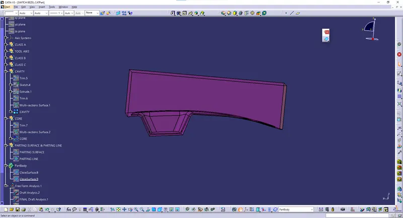
Creating Solid Body:
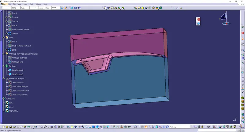
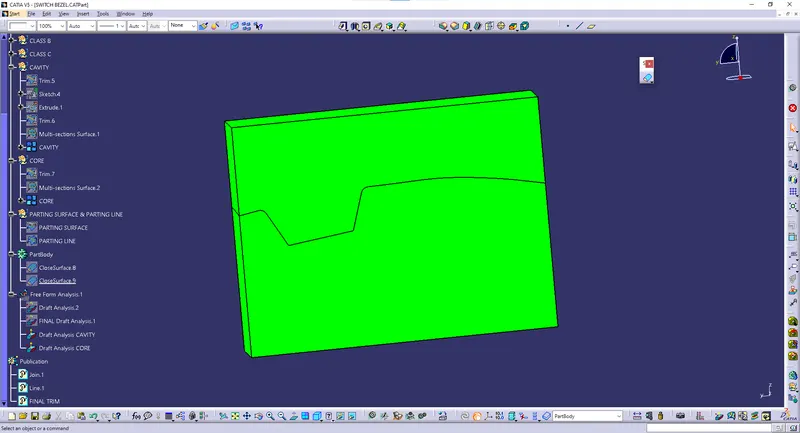
- The Core and Cavity were made into a solid component using the Close surface feature.
- The Tooling axis, Core, Cavity, Parting surface and Parting line were published.
SOLID BODY:
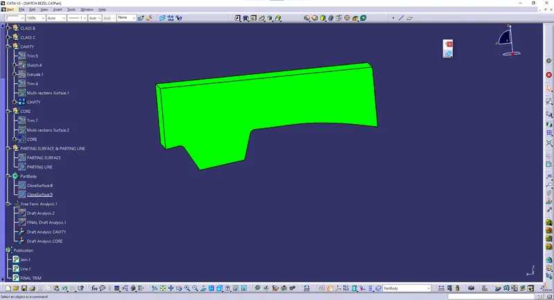
DRAFT ANALYSIS CAVITY:
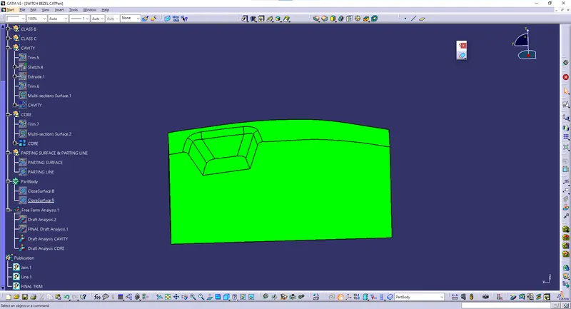
DRAFT ANALYSIS CORE:
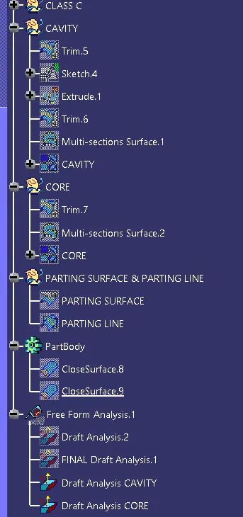
TREE STRUCTURE:
CONCLUSION:
Created the Core and cavity blocks for the switch bezel designed in the earlier challenge.