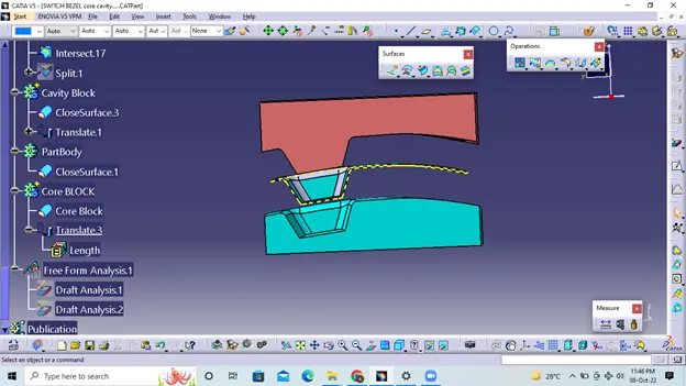
Week 8 - Challenge 6 - Core & Cavity Design
Tolling axis:-
It is the direction in which the mold opens and closes, the bevel angle that needs to be provided when considering this tool axis.
We can create the tool axis using the bisecting method.
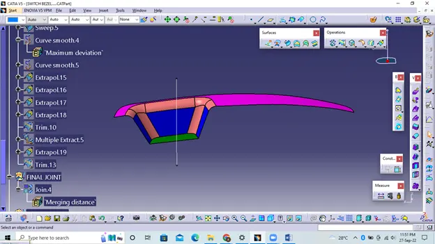
CLASS A SURFACE DRAFT ANALYSIS:-
From the picture you can see that one side of the part fails the feasibility check, this happened because of the bevel angle given to the axis at the beginning. To prevent this, the angle must be increased again and an update must be performed.
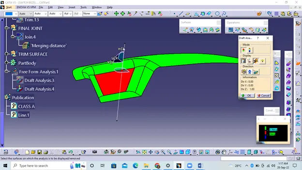
CLASS B SURFACE :-
To create a Class B surface, the required surface except for the offset surface was extracted and then the entire surface was cut away.The entire surface was then extrapolated to obtain the intersections between them.Because the thickness of the switch frame is 2.5mm.
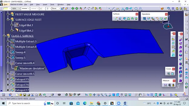
CLASS C SURFACE:-
The desired outer edges of the A-surface were extracted using Multiple Extract. To avoid patches, the curve is smoothed using the smooth curve option. Then, using the Sweep command, the surface was created
After using the extrapolate command, the edges were intersected between the corners of the surface, which facilitates the clipping operation. Now the desired part of surface C has been cut.
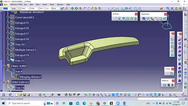
Close Surafe Creation:-
Now the Class A and Class C surfaces have been joined together by removing the gaps between them using extrapolation and Surface Trim. Then the exact surface of the switch bezel was cut from the height of the resulting trim surface with a class -B finish.Then defining the body of the part using the closed surface command in Part Design creates a solid part body.
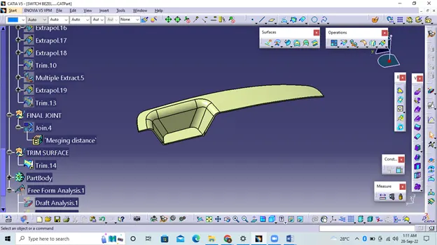
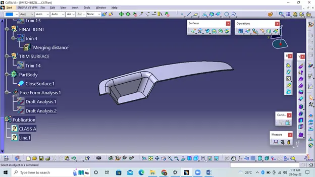
Close Surface Draft Analysis:-
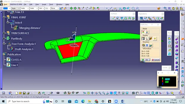
Core And Cavity Design:-
The mold core and cavity are the molded parts in either half of the mold tool that give the plastic product its final shape.
Hot molten material is injected into the core and cavity and then hardened into shape. The design of the core and cavity is critical to the correct creation of the product. The sequence of events during the injection of a plastic part into a mold is called the injection cycle.
The cycle begins when the mold is closed, followed by injection of the polymer into the mold cavity.
The core is usually made of the highest quality sand and is placed in the desired position in the mold cavity. Core impressions are added to both sides of the pattern to create impressions that allow the core to be supported and held at both ends.
Core:-
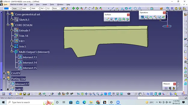
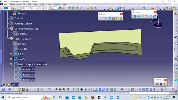
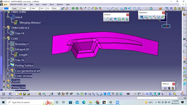
Core construction begins with the removal of a parting face that will become the base for the core and cavity. The parting surface is in most cases maintained at a class B surface to prevent tight and close contact between the core and the cavity.
First, the class A surface is extrapolated with a certain length, and later it is clipped by the C surface
Cavity:-
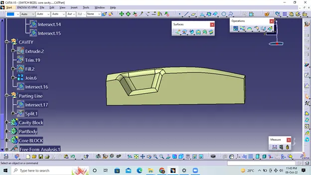
The cavity is the part where the molten plastic is injected and filled. The hollow block is prepared by first extruding the outer edge in the machining direction.
Parting line:-
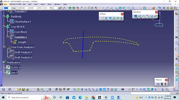
The parting line in industrial mold casting is the boundary line where the bevel angles change direction. That is, it is the parting line that separates the core and cavity halves of the molded part. Sometimes this is the starting point for the parting face of the mold.Here, the intersection of the parting face, core and cavity in the ZX plane gives an intersecting line called parting line.
Parting Surface:-
The parting surface of the mold is those surfaces of the two mold plates adjacent to the impressions that touch each other to form a seal and prevent loss of plastic material from the impression. The parting surfaces of the mold are parts of both.
molding plates, adjacent to the impressions, which fit together to form a seal and prevent loss of plastic material from the impression.