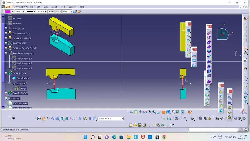
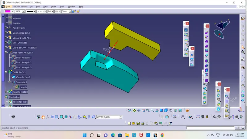
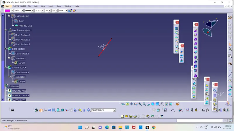
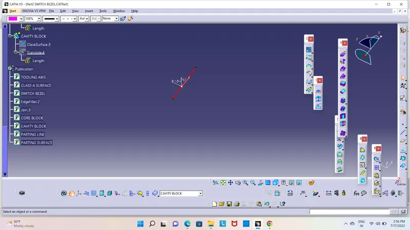
Week 8 - Challenge 6 - Core & Cavity Design
AIM : Create the Core and cavity blocks for the switch bezel .
The core is the part which forms the internal shape of molding.
The cavity is the part which forms external shape of molding.
Core is the side of the tool where the plastic part is injected from; also known as the bottom half of
the tool. The upper half of the mold is called CORE.
A tool with one impression is often called a single impression (cavity) mould.
A mould with two or more cavities of the same parts is usually called a mulitiple impression mould.
The outside of the enclosure will be a cavity in the A-side of the mold and the inside will be
a core on the B-side.
Gonna work the parting line and the parting surface.
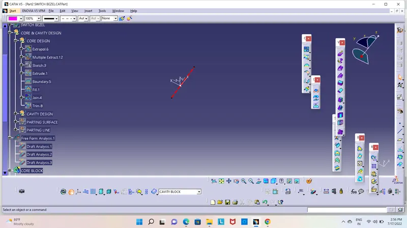
first insert the geometrical set and named it as CORE & CAVITY DESIGN
First we design the core side
in the generative shape design.
extract the boundary of class A.
AND extrapolation the boundary
and extrapolation the class A.
length 12 mm
curvature and tangent
click ok.
unhide the class B surface and joinwith the class C.
Trim the class A with the C surface.
Unhide the axis system. and sketch rectangular,
ensure it is in the part.
extrude the sketch .direction: tooling axis.
ok.
trim the extrude and class a+c surface now we get the core
and go to the part design and close the surface
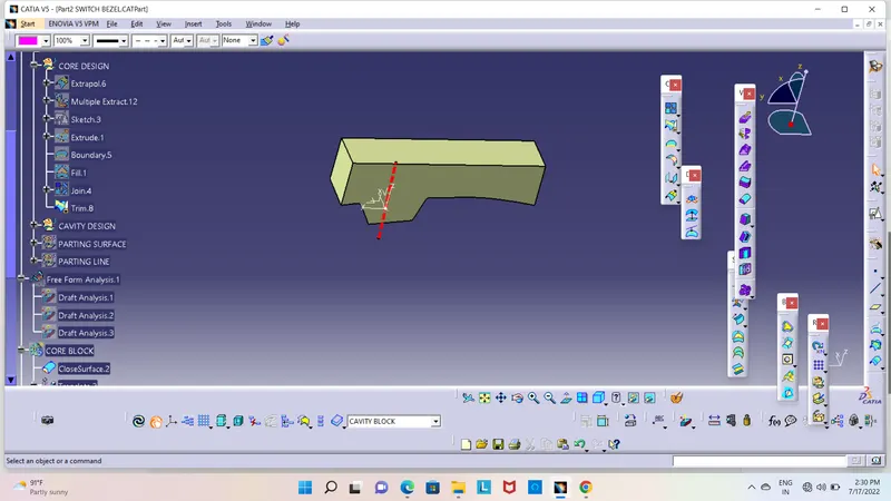
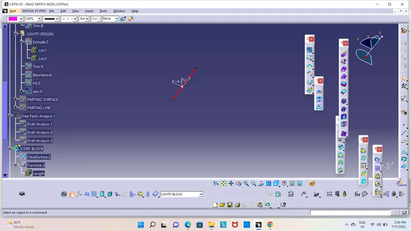
CAVITY DESIGN
extrude it ----- parting the sketch----tooling direction.
unhide the B surface trim
and trim it--- extrude and b surface.
go to fill----create boundary.and fill the boundry.
Insert a body and make a solid it.
click the closed and right click join.
join the fill and trim.
now this the core closed
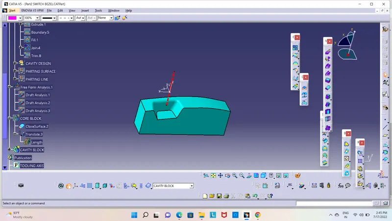
DRAFT ANALYSIS OF BOTH CORE AND CAVITY PARTS
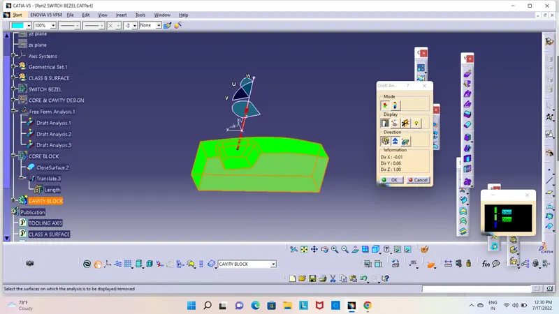
It shows 3 deg of draft angle
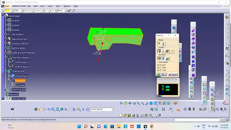
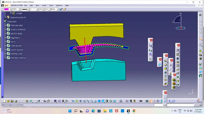
using the translate command in tooling direction core block is +ve direction 80 mm distance
cavity is -ve direction translated.