Week 8 - Challenge 6 - Core & Cavity Design
Core and Cavity Report
Aim:
- To create Core and Cavity for the given switch bezel.
- To create parting line and parting surface.
Objective:
Switch Bezel
- To create the Final Solid Part by using the given Class A.
- To create the Tooling Axis for the Class A and Final Solid Part.
- To Draft analysis the obtained Final solid part and Class A using the created Tooling Axis.
Core and Cavity
- To create Core and Cavity for the given switch bezel.
- To create parting line and parting surface.
Introduction
Tooling Axis
- The Tooling Axis is to show in what direction does the core and cavity moves.
- It also created to give a draft angle for the final solid part.
Draft Analysis
- The draft analysis is done on the basis of the Tooling Axis in order to find whether the final product is done as per the Design rules.
- The Draft angle which is assigned to the Tooling Axis defines the analysis.
- The Nominal Draft angle for the plastic product is 3 degree.
Class A
- Class A is the aesthetic surface.
- Class A is created on the basis of a concept sketch or by the predefined shape on basis of the design engineer and customer requirement.
- Class A is given to the Product design engineer in order to get the final solid part.
Class B
- Class B is the surface that is created by the product design engineer in order to get the final product from the class A surface.
- Class B is created based on the thickness that the final solid part should be.
- In other words, Class B is an Extended version of Class A with some thickness gap between them.
Class C
- Class C is the surface that is designed by the product design Engineer.
- Class C is created inbewteen Class A and Class B in order to connect them.
CAVITY
- Cavity is known as the ‘Female-Section’ of the mold that creates the external shape of the plastic component.
- It belongs to the fixed-half section of the mold-unit.
- It is usually formed by removing metal from the mating surfaces of the two halves.
- Molds can contain a single cavity or multiple cavities to produce more than one part in a single shot.
CORE
- Core is known as the ‘Male-Section’ of the mold that creates the internal shape of the plastic component.
- It belongs to the moving-half section of the mold-unit.
Parting surface
- Parting surface is layer between the core and cavity of a mold.
- If the parting surface is not designed properly the product which comes out of the mold will have defect.
- It should be tightly closed so the molten material will flow in correct path.
Parting line
- Parting line is a line where cavity meets the component.
- In other words parting line is extactly where cavity and core touches with product.
Procedure:
Switch Bezel
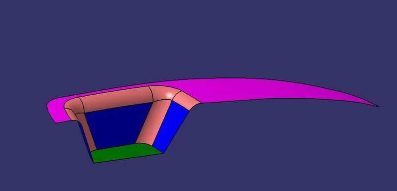
Class A
- The class A is taken as given Catpart file.
- Created class A is checked with the boundary tool.
Tooling Axis
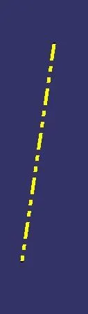
- The tooling axis is created using bisecting method.
- Bisecting method is one method for creating the tooling axis where tooling axis created by intersecting two line.
- The axis is created by extrectin the surface and creating a point on the surface.
- The two line, one line is created from the intresect of created y-axis and class A.
- The second line is from intresect of created z-axis with class A.
- Then orginal tooling axis created.
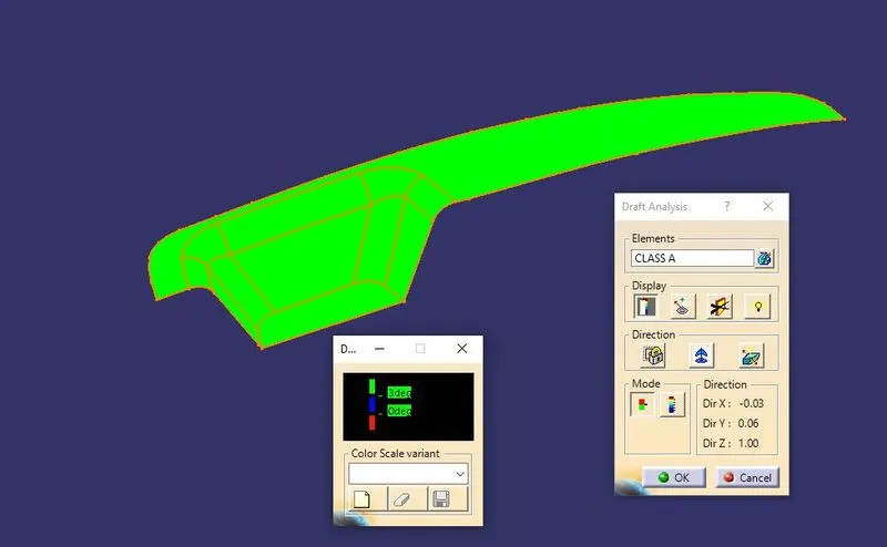
Draft Analysis on Class A
- The draft analysis is done on class A with the help of tooling axis.
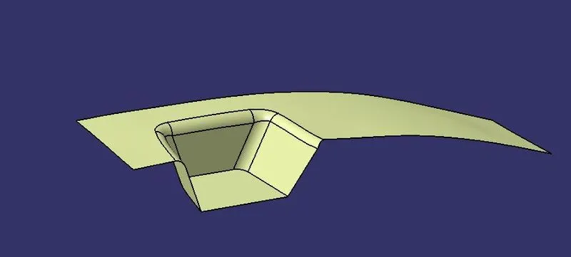
Class B
- The class B is created by offsetting the derived Class A to 2.5mm.
- The Faces of class A is Extracted and untrimed sperately.
- It is done seperately due to fillet that will not be proper when offset.
- The untrimed faces are offseted.
- The trimed together and Edge fillet operation done.
- Thus the class B is derived.
Class C
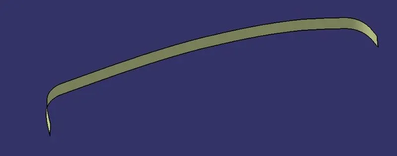
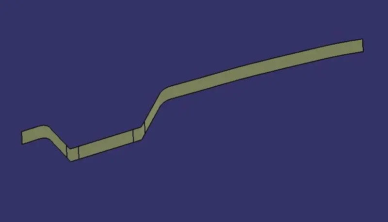
- The class C is created from the class A using the sweep.
- The boundary of class A is taken.
- Then 'with draft direction' is selected in the sweep tool.
- The tooling axis is used for draft direction and boundary as profile.
- The Class C is created.
Final operation
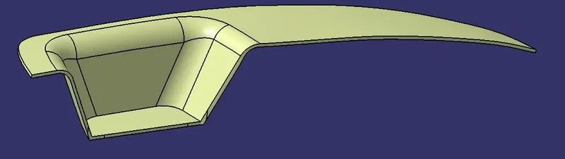
- The Created class C is joined with the class A.
- The joined class A and class C is trimed with class B.
- If class A and class C join can't be trimed with class B then extrapolate the class B to some millimeters.
Solid Body
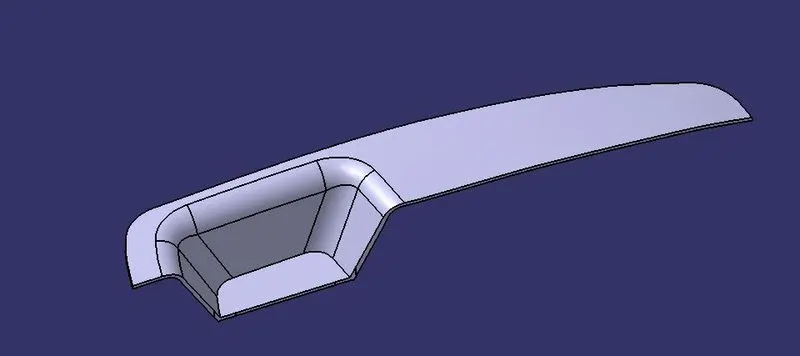
- The solid body created by using closed surface.
- The design which created is switched from 'genrative shape design' to 'part design'.
- Then closed surface tool is used to convert the plastic design model to solid form.
Draft analysis
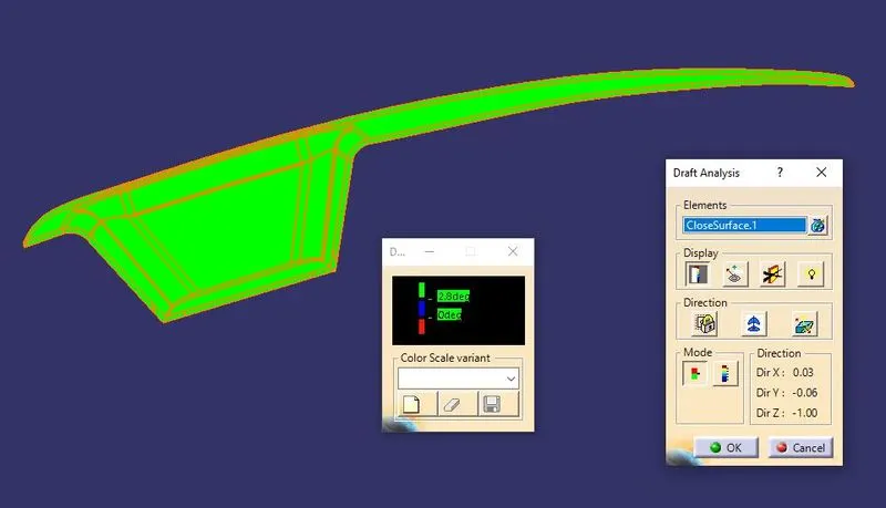
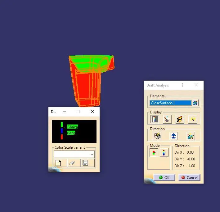
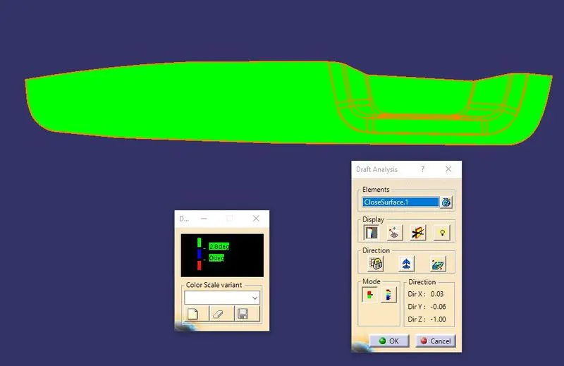
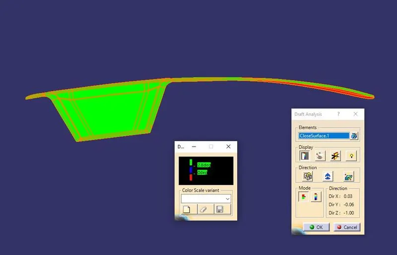
- The draft analysis on solid body is done.
- The draft analysis show the created solid is done as per design rules.
Core and Cavity of Switch Bezel
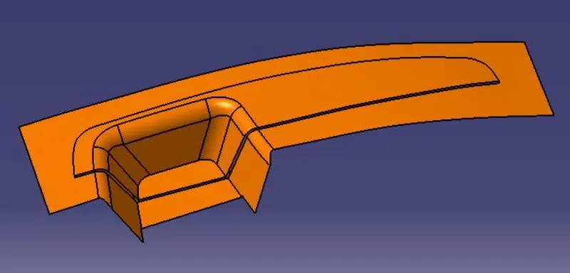
Parting Surface
- The parting surface is created by design rules.
- It is created by joning the class A and Class C.
- Then triming it with class B.
- The parting surface shows us where does the core and cavity are going to meet.
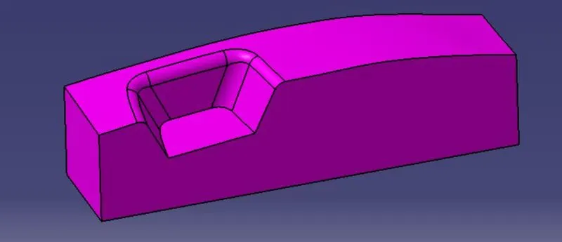
Core block
- Core block is where the required compenent impression will have init.
- Then for the creation of core block a sketch of rectangle is created and it is extruded.
- The extrude done in the tooling axis direction.
- The extrude is then trimed with parting surface.
- The Core block trimed in the upward direction.
- There is open in the top it closed with extrude process.
- Both the extrude are joined together to form the closed object.
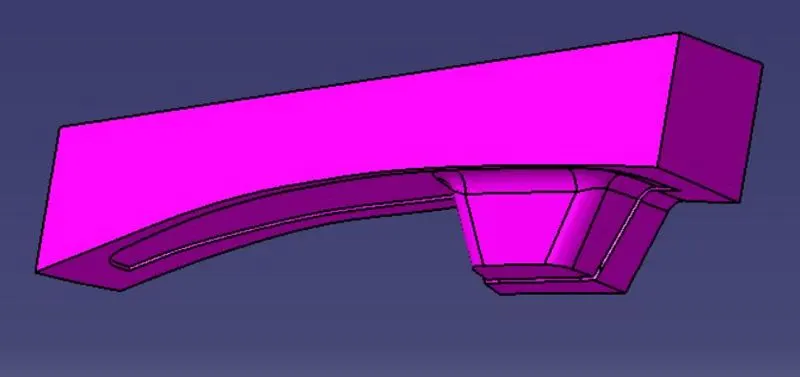
Cavity block
- Cavity block is where the required compenent will be covered.
- Then for the creation of Cavity block a sketch of rectangle is created and it is extruded.
- The extrude done in the tooling axis direction.
- The extrude is then trimed with parting surface.
- The Cavity block trimed in the doenward direction.
- There is open in the bottom it closed with extrude process.
- Both the extrude are joined together to form the closed object.
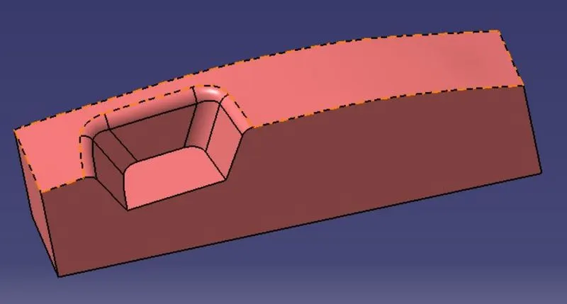
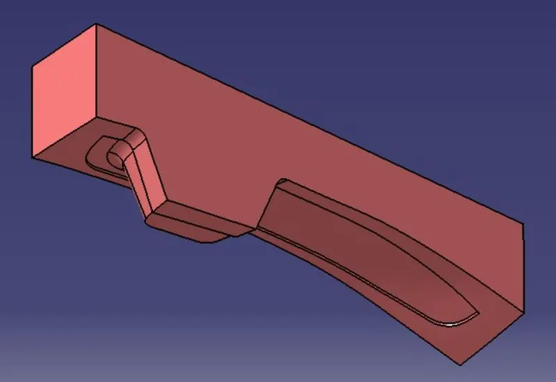
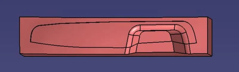
Core and Cavity Solid
- The Created core and cavity surafce block is checked for any opening.
- Then it is converted to solid by switch from 'generatiive shpe design' to ' part design'.
- The 'closedsurface' option is used to get solid.
Isometric view
Front View
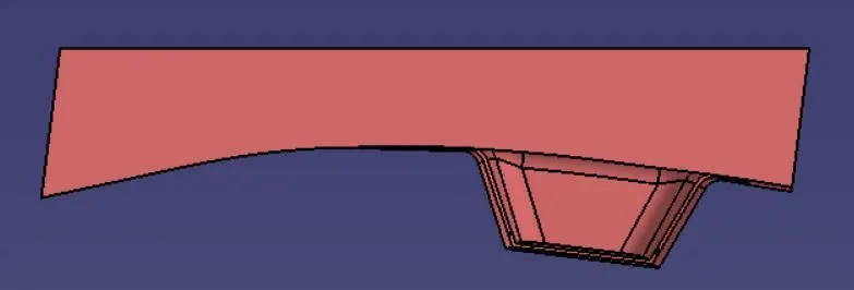
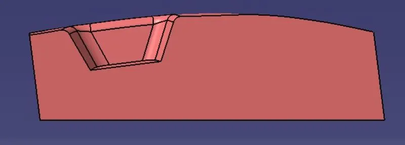
Side View


Top View
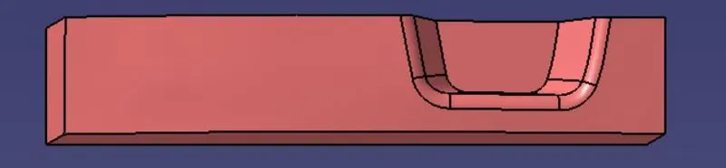
Parting line
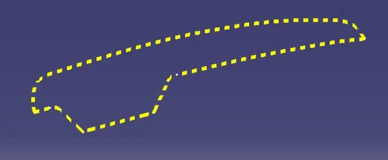
- The parting line is created by intersecting method.
- The class A and Class C join is taken and intersected it with the Class B.
- The line which is formed is called parting line.
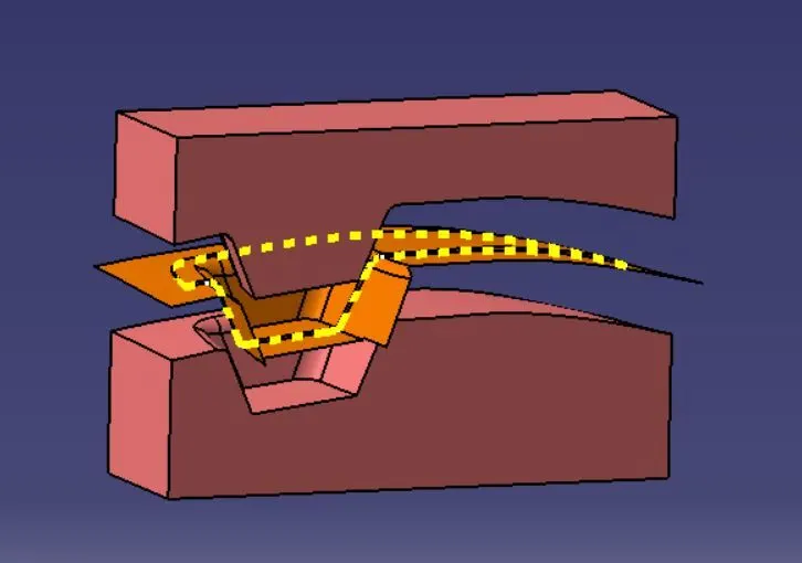
- Then translate option is used.
- Inorder to show the component, parting surface and parting line in between the core and cavity.
- The Core is translated upward and Cavity is translated downward.
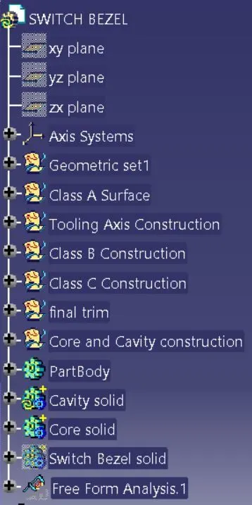
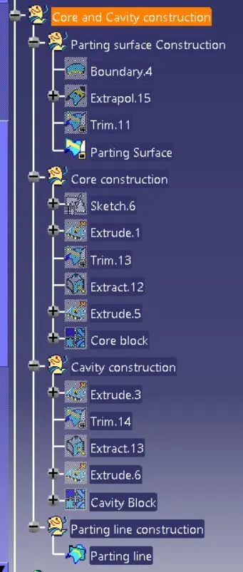
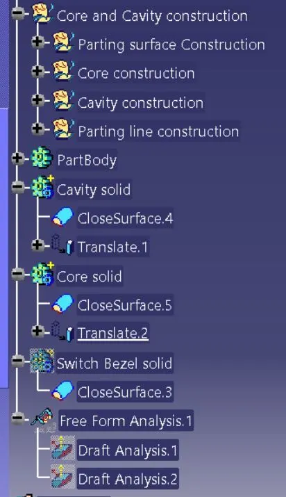
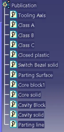
Srtuctural tree Images
Conslusion
- Thus the Core and Cavity for the Switch Bezel is created.
- The Parting surface and parting line created in accordance with it.
- The draft analysis for the Switch Bezel surface and solid is done and its satfies the design rules.