Week 8 - Challenge 6 - Core & Cavity Design
Core & Cavity Design for switch bazel
OBJECTIVE
- To create the Core and cavity blocks for the switch bezel design.
INTRODUCTION
- Core and cavity is another name of Mould pattern it is using for produce the component by using injection moulding so we need core and cavity based on the components design.
DESIGN CONSIDERATION
- Class – A surface are created on all visible exterior surfaces using alias.
- Class – B surface have engineering feature like ribs etc.
- Class – C surface should be pass on draft analysis.
Core & Cavity Design steps
1) Parting surface
2) Core
3) Cavity
4) Parting Line
Parting surface
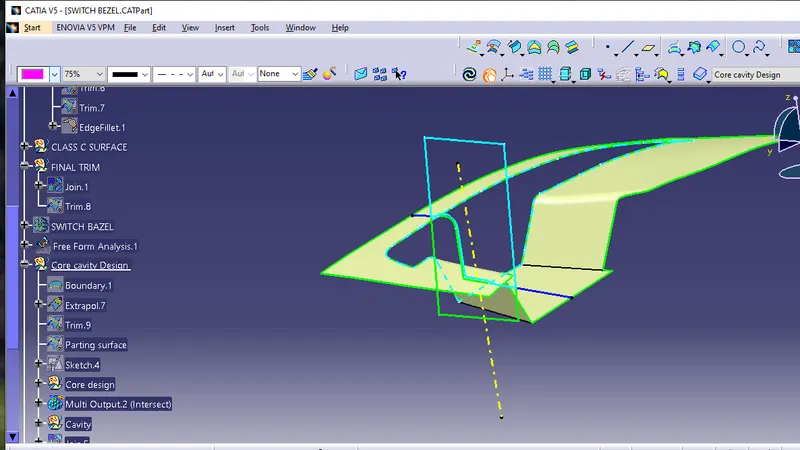
Fig.1.1 Parting surface
The parting surface was trimmed with an extrude (with reference anlge of tooling axis) of a rectangle that enclosed the component design that resulted in creation of core block.In industrial casting of molds, is the border line in which draft angles change direction. One can check the parting line in the mould or product which divides the two half the core and cavity of a molded part. It is starting for molding parting surface.
Core
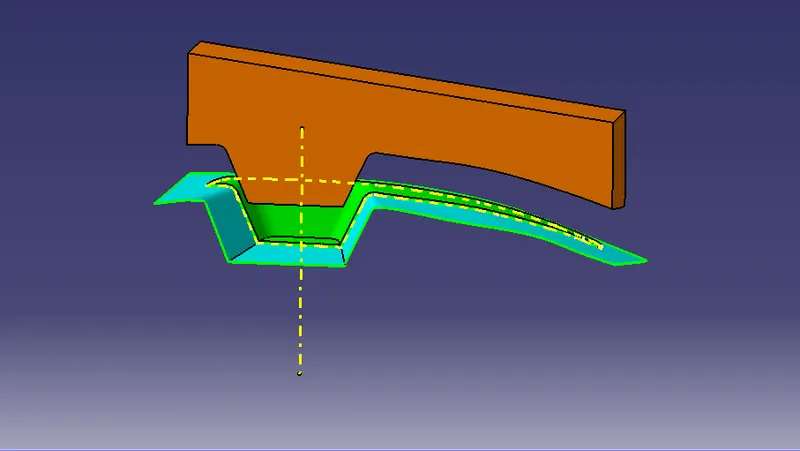
Fig.1.2 Core
- Create a sketch with rectangular shape which should not exceed the trimmed surface.
- Extrude the sketch along the tooling axis and trim it with the other surface.
- Select the boundary and close the extruded surface using fill command and the final surface is created
- Go to part design create solid surface using the close surface feature
Cavity
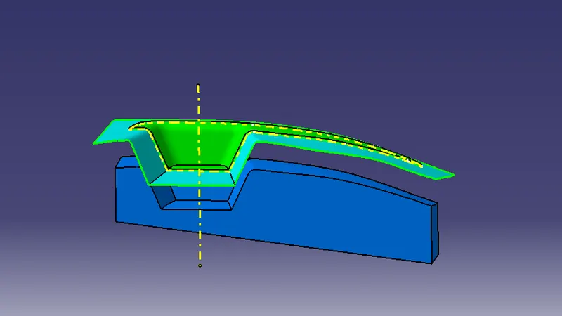
Fig.1.3 Cavity
The CLASS B surface was trimmed with an extrude of rectangle along the tooling axis.
Parting Line
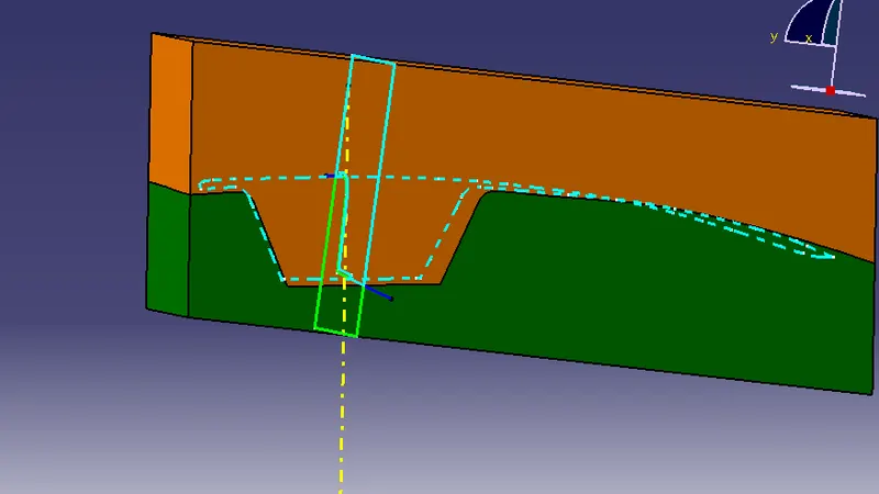
Fig.1.4 Parting Line
During the injection molding process, the core and cavity blocks are pressed tightly and form a sealed hollow mold cavity, the pressed surface is called the parting surface. In other words, it is a surface that separates the mold block into two parts – the core and the cavity.
Parting Line Creation
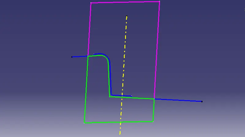
Fig.1.5 Parting Line Creation
MOULDING WAY
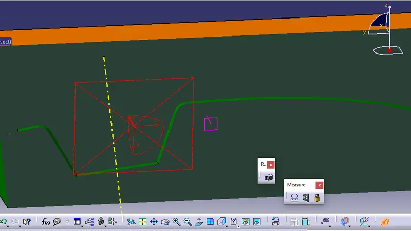
Fig.1.6 Moulding way
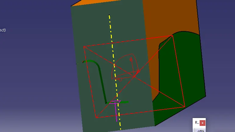
Fig.1.6 Moulding way
CORE & CAVITY IN VARIOUS VIEWS
The Mould Core & Cavity are the two halves of the mold where the hot materials is injected into the core and cavity and the gap between the core and cavity is filled with the hot molten materialduring the injection moulding process and then hardened into the final shape.
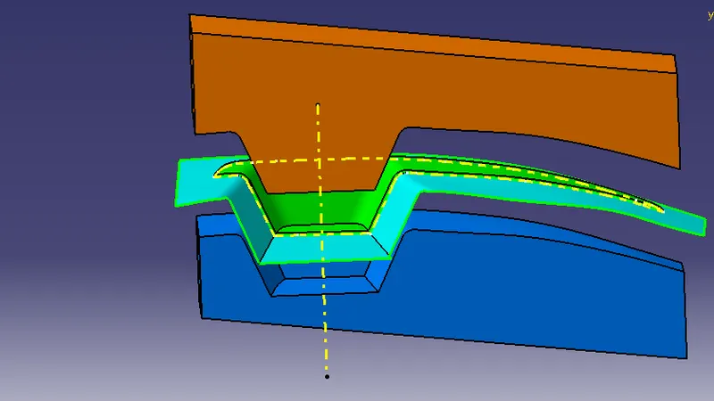
Fig.1.7 Front view of core and cavity
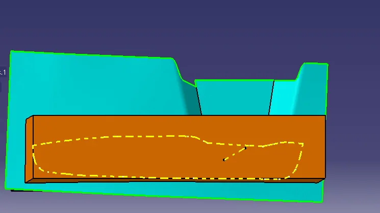
Fig.1.8 Top view of core and cavity
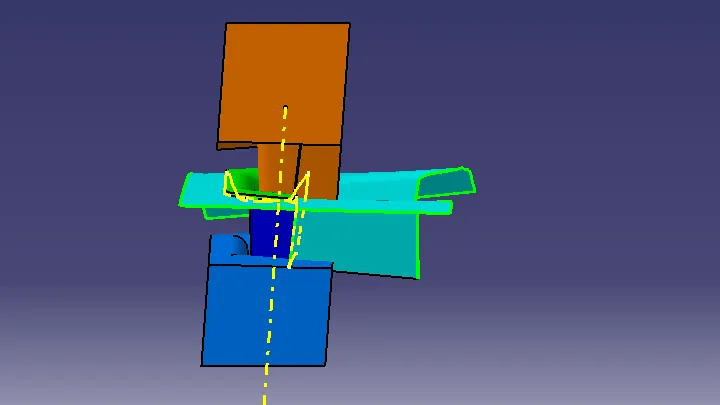
Fig.1.7 Side view of core and cavity
RESULT

CONCLUSION
The above core and cavity is designed by given parameters.
It was designed by catia V5.
The tree sturcture is maintained properly.