Week 8 - Challenge 6 - Core & Cavity Design
AIM:
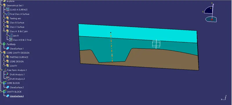
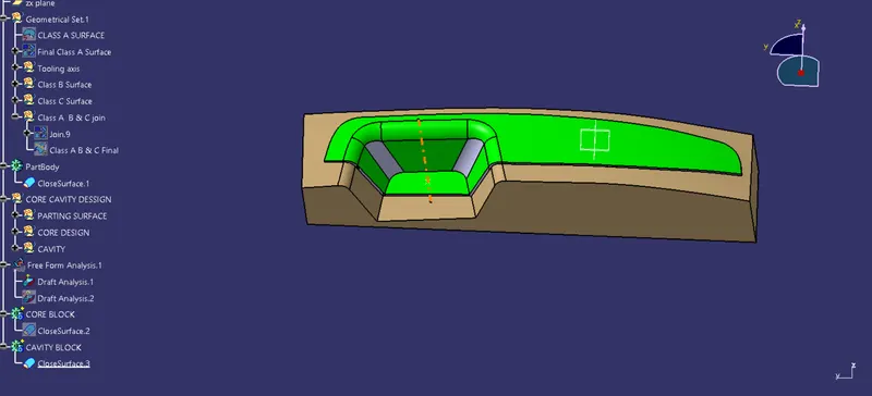
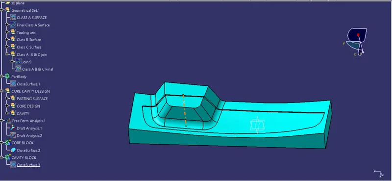
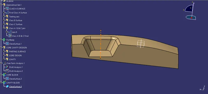
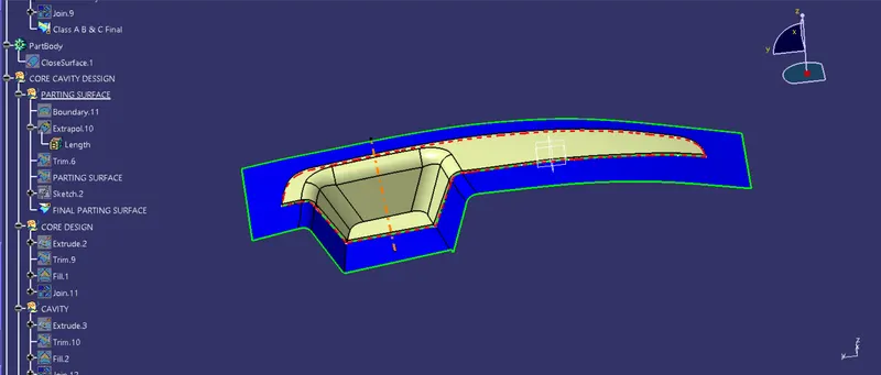
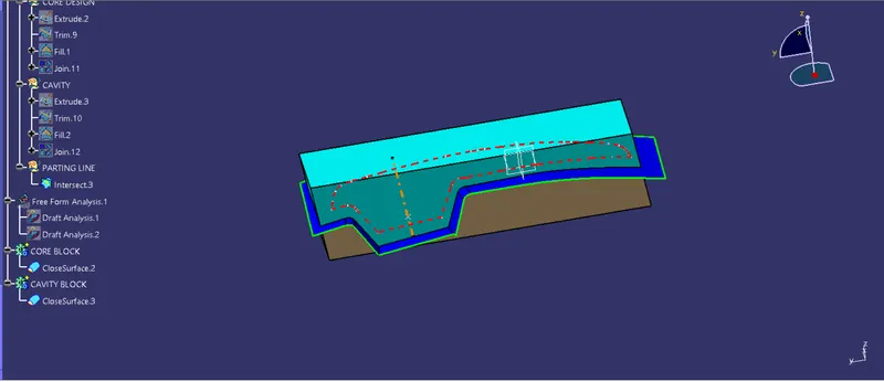
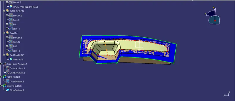
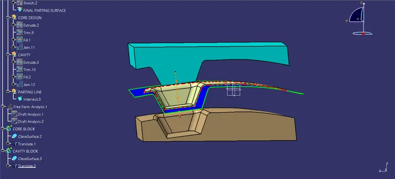
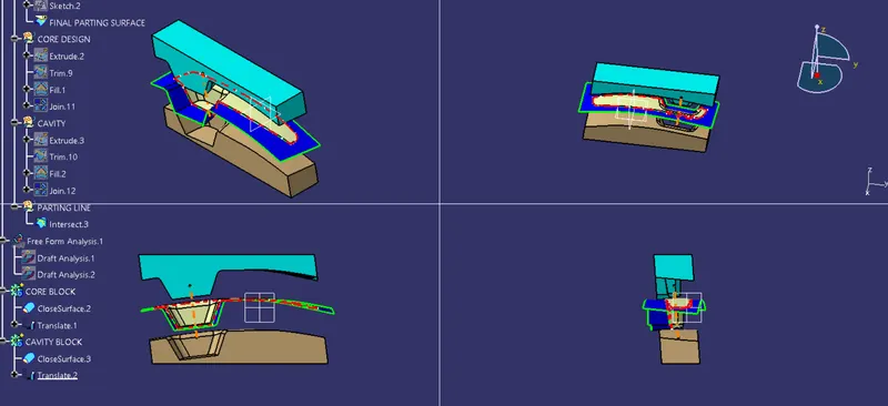
- To Create the Core and cavity blocks for the switch bezel component.
DESCRIPTION:
1. CREATING TOOLING AXIS -
The Tooling Direction is basically the direction that the mold pulls a part. The mold is built in two separate pieces, basically. You have a Cavity side and you have the Core side. The Core pulls apart from the Cavity and that's the Dye line or the Tooling Direction.
- Open the given CAT part file.
- Check for gaps between surfaces for that click on join and then preview.
- If theres any gap between the surfaces join them with a maximum tolerance of 0.003 mm.
- Extract the boundary and dissemble the boundary.
- Find the correct tooling axis where the material don't interfere with the tooling axis and all the elements can be created.
- Create an axis system using at the centre of the switch Bezel.
2. CORE DESIGN
- Core - A portion of the mold that goes inside a cavity to form the interior of a hollow part.
- Core-cavity - A term used to describe a mold created by mating A-side and B-side mold halves.
3. CAVITY DESIGN
- A mold is a hollow form typically made from stainless steel that has plastic injected into it to manufacture a plastic part.
- The plastic is inserted into the mold cavity, which is a hole in the mold shaped like the desired part.
CONCLUSION:
- The Core and cavity blocks for the switch bezel component is created.