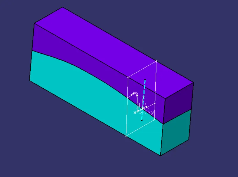
Week 8 - Challenge 6 - Core & Cavity Design
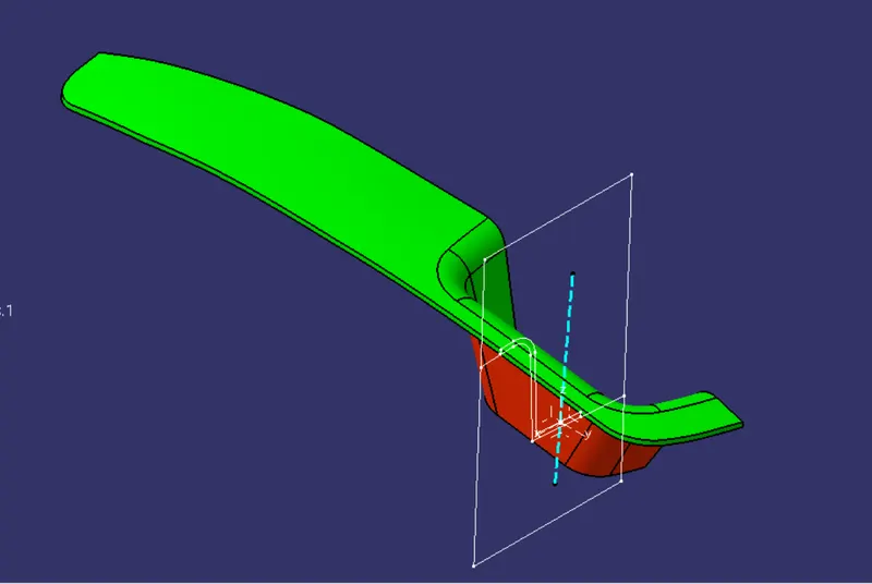
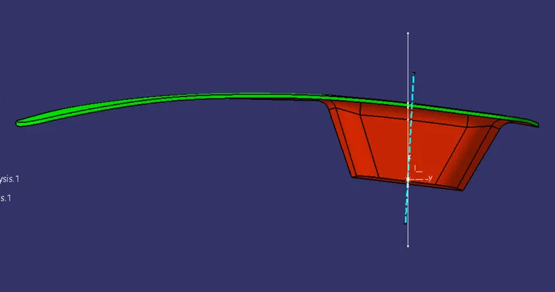
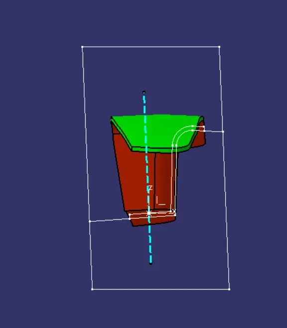
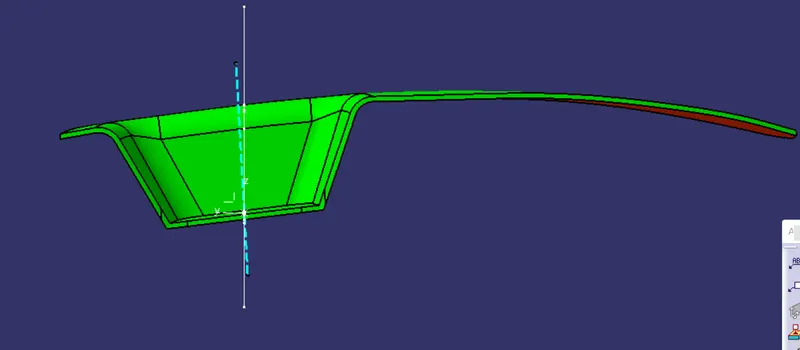
AIM: TO DESIGN SWITCH BEZEL USING CLASS A SURFACE AND PERFORM DRAFT ANALYSIS ON THE DESIGN
Procedure:
- Check the boundary and ensure the class A surface form a continuous boundary.
- Tooling axis is created with bisection method. Intersection of the class A surface with a plane is made and the edges which are parallel were bisected to form a line and later this line in bisected with another line in X-Z plane view. The line thus fomed is considered as tooling axis.
- Draft analysis is performed to verify the tooling axis direction
- The surface of switch bezel are extracted. on these extracted surfaces operations such as Untrim and extrapolate are performed and later these are offset by a distance of 2.5mm to form a class B surface.
- Class C surface is made through the boundary and Class C and Class A are joined.
- The joined Class C and A is trimmed with Class B to form a closed part.
- Using Closed surface feature in part design a solid part is made.
- Draft analysis is performed on the solid body finally.
CORE AND CAVITY DESIGN
- A sketch with rectangle profile is drawn. The area of the rectangle covers the switch bezel. The rectangle sketch is extruded and is trimmed with Class A and C joined surface to create outer surface of the Core block.
- Boundary of the open layer is taken and fill command is used to create Core Block.
- The same processis used for designing cavity block
- Intersection of core, cavity and switch bezel is taken.
- parting line is formed by Intersection of class B with switch bezel
- Parting surface is formed by Trimming class B with parting line/Switch bezel.
- Class A, Tooling axis, Parting line and parting surface are published