Week 8 - Challenge 6 - Core & Cavity Design
Core & Cavity Design
Aim
Create the Core and cavity blocks for the switch bezel designed in the earlier challenge.
Objective
To Design a Swith bezel in CATIA V5 using the given Class A surface and design parameters and create a core and cavity .
Input data
We use class-A- surface as an input data
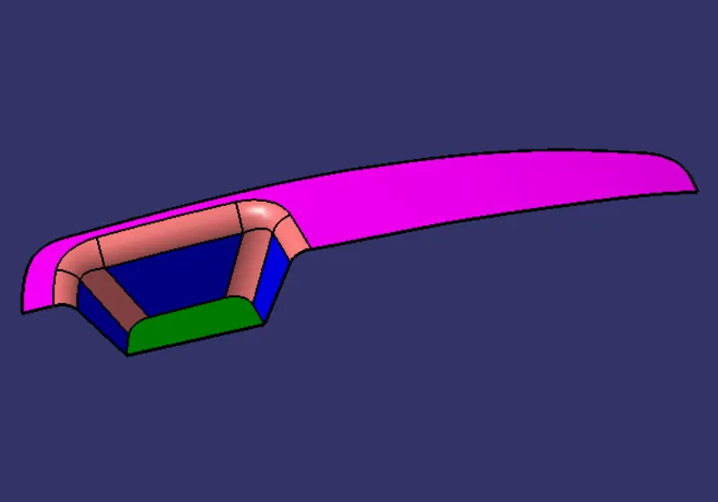
Tooling Direction
Tooling direction in which 2 halves of the mold get separated against each other. There are a lot of methods available to create a tooling direction, in this case, am going to use the bisecting method.
In this model am going to use bisecting method, my tooling direction in Z direction and I have a flat surface in the Z direction so am going to extract the flat face and, create a point at the center of the surface. and create a line along with the point in Z direction, Create axis system at the point and draw a new sketch on ZX plane of the axis system and create intersection curve through the surface by using ZX plane and draw a line on the intersection curve make sure the line is parallel to the dummy tooling axis and create one line at the center on the axis system and give 5 degree angle from the intersection line.
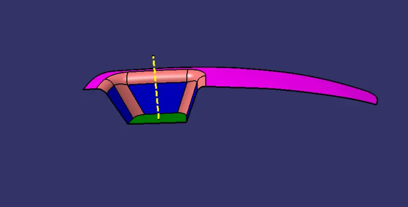
B-Surface creation
As usual B surface is created using the standard procedure by extract, un trim, extrapolate, join,Trim,split and offset commands. The B-surface is created parallel to the A-surface.
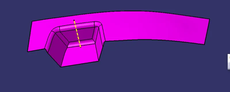
C- Surface creation
Class C surface for this component is created using the sweep command. All the ends of the component surface were facing downwards, so the C surface will create perpendicular to B surface.
To create a C-surface we need to extract the boundary of the A surface by using multiple extract command then create sweep with draft direction(Tooling direction) with 3 degree of positive draft angle .
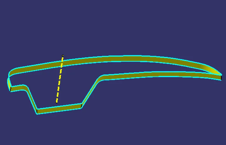
Features Used
- Extract
- Offset
- Trim
- Untrim
- Split
- Swept
- Fillet
- Multiple extract
- Join
- Extrapolate
Feature Tree
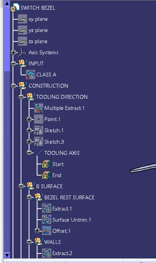
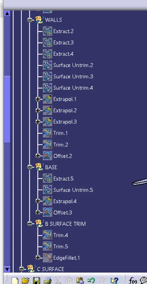
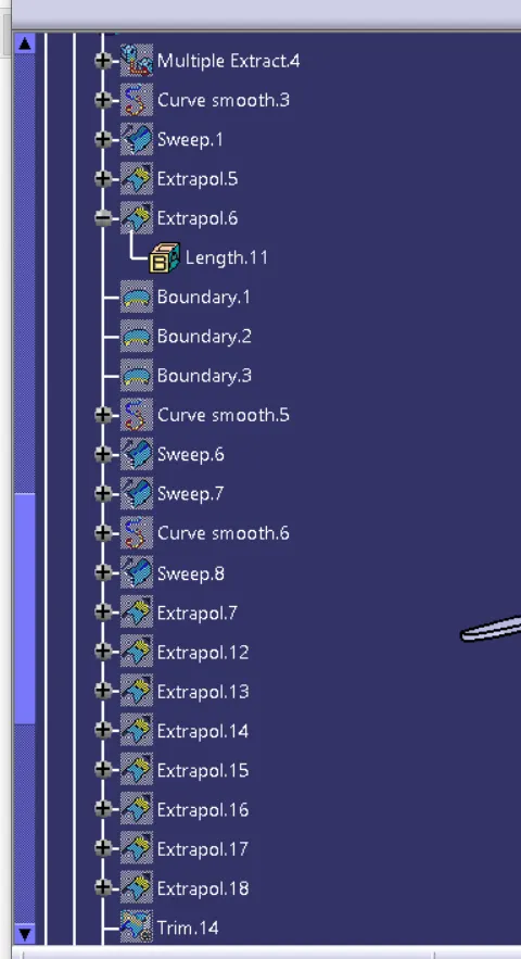
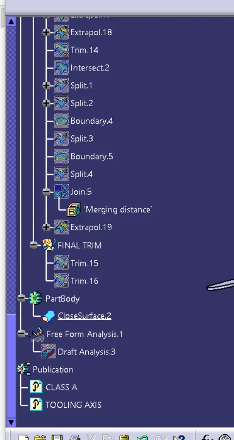
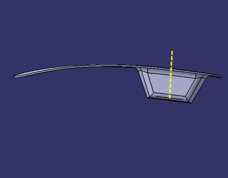
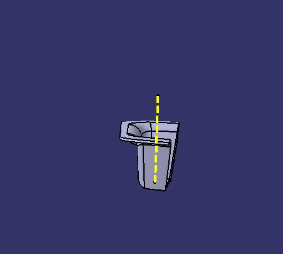
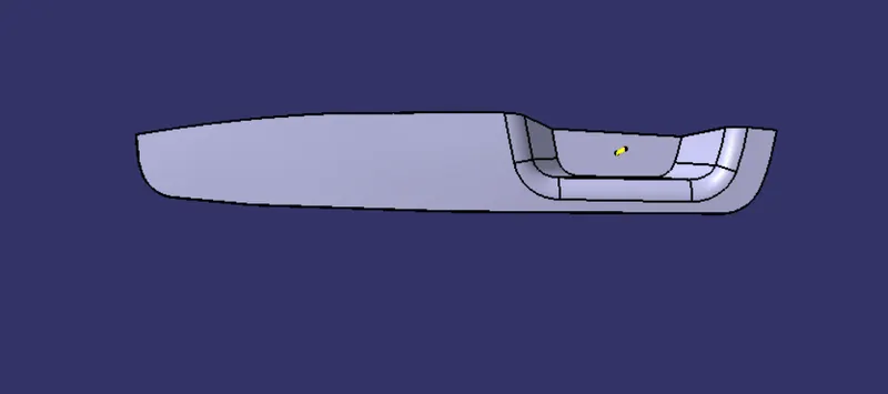
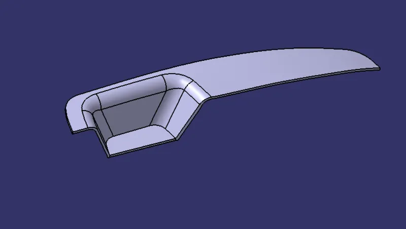
Different views
Front view
Right view
Top view
Isometric view
Converting into the solid model
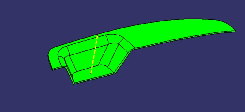
Once all surfaces are created Class A, B, and C surfaces are joined together to get the final closed volume. The closed volume is then converted into a solid body using the closed volume command in the part design workbench.
Draft analysis
The Draft Analysis allows the user to easily analyze a part for a proper draft angle and check to the manufacturability of the component.
Core and Cavity Design
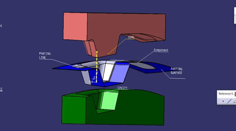
The core & cavity are the shaped sections in either half of the mold tool which give the plastic product its final shape. The hot molten material is injected into the core & cavity and then sets hard into shape. The design of the core & cavity is essential in the correct formation of the product.
- The core is the convex region (also called the male part of the mold), which forms the inner surface of the component which is being molded.
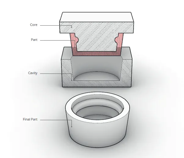
Core design
- The core is the convex region (also called the male part of the mold), which forms the inner surface of the component which is being molded.
- The core design started with extracting parting surface and that becomes datum for the core and cavity.
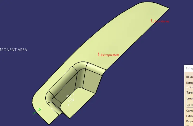
- create one boundary with point continuity from the outside edges of the class-A-surface and extraploting with the length of 15mm and trimmed that extrapolating surface with C surface
- Again trimmed the surface with B surface
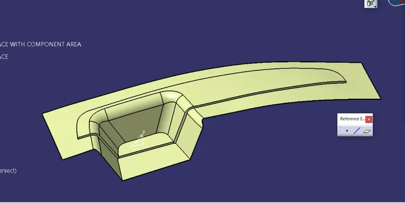
- Then the rectangular block is created and extruded along with the tooling direction
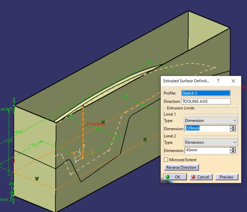
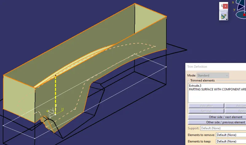
- Then this rectangle surface trimmed with the parting surface
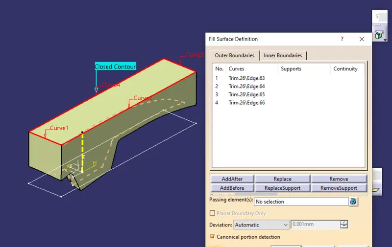
- We need to close the top side of the core for that we use the fill command and close the opening surface or you can use multi-section surface command to close the surface.
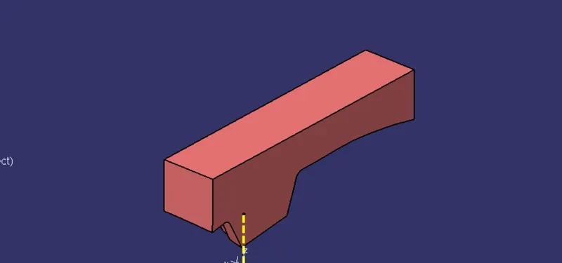
- After fill the surface then join them together and convert the surface into solid
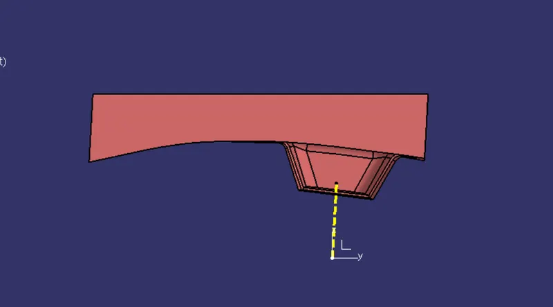
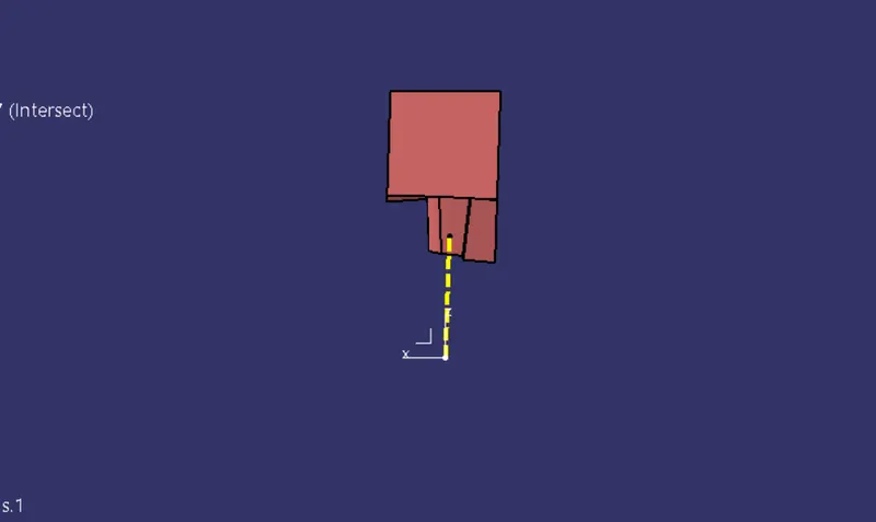
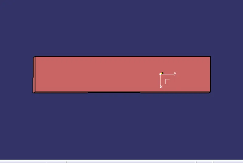
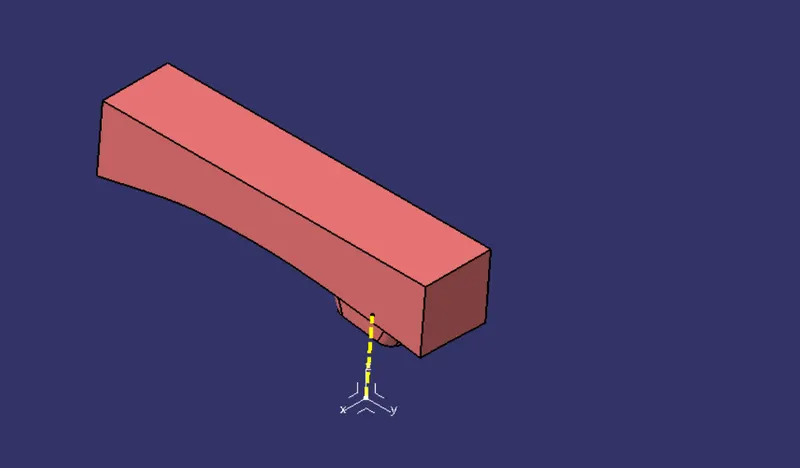
Different views of the core
Front view
Right view
Top view
Isometric view
Cavity Design
- The cavity is the depression or the concave region (also referred to as the female portion of the mold) and forms the component's outer surface.
- Molten plastic to enter the fixed side (mold) its made the concave space.
- Fixed side mold cavity molds
- To create cavity first we need to create the parting surface, for that we use B surface as the parting surface
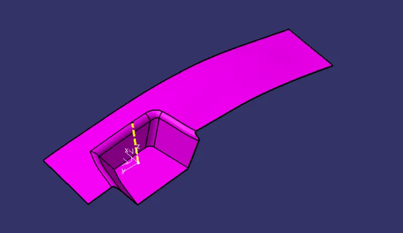
- Then create one rectangle surface along with tooling direction use the same sketch for cavity also
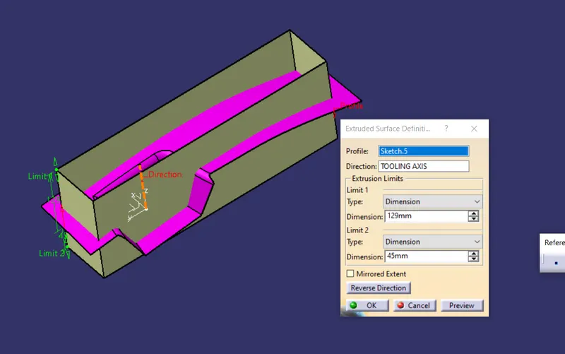
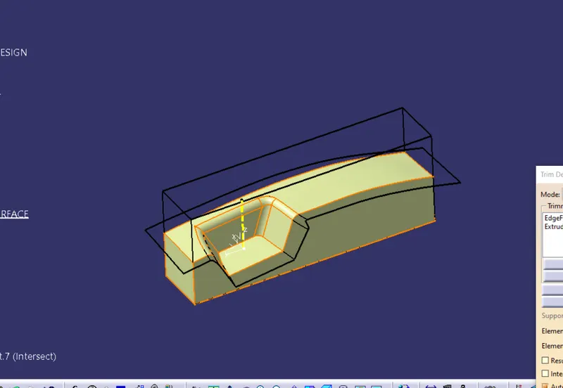
- Then trim the rectangle with parting surface(B surface)
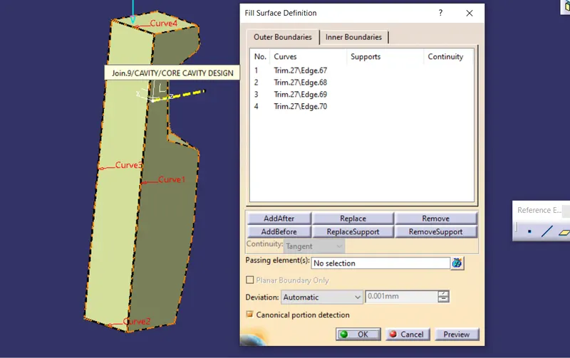
- Then close the bottom surface by using the fill command and join them together and convert surface into solid
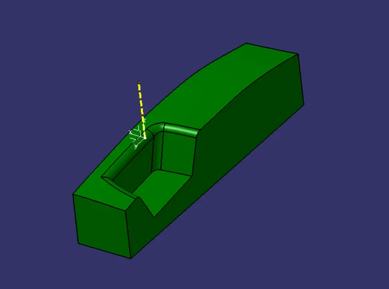
Diffrent views of the Cavity
Front view
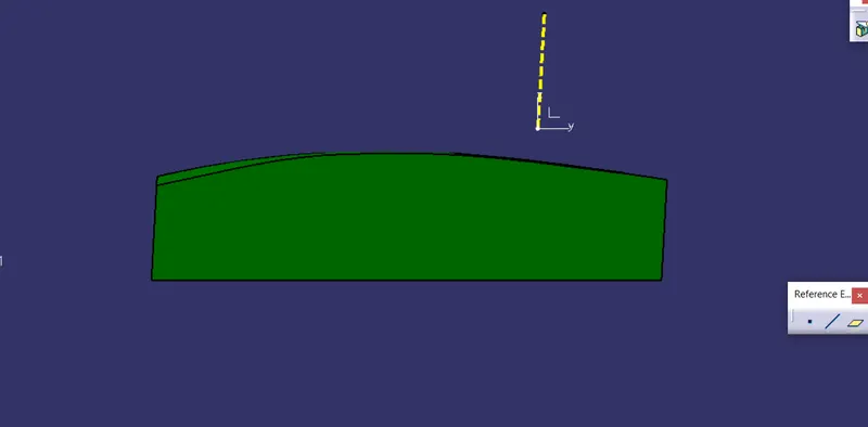
Right view
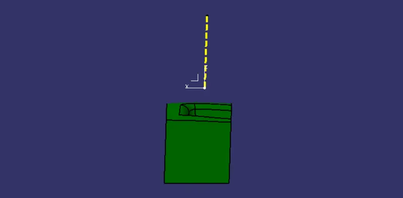
Top view
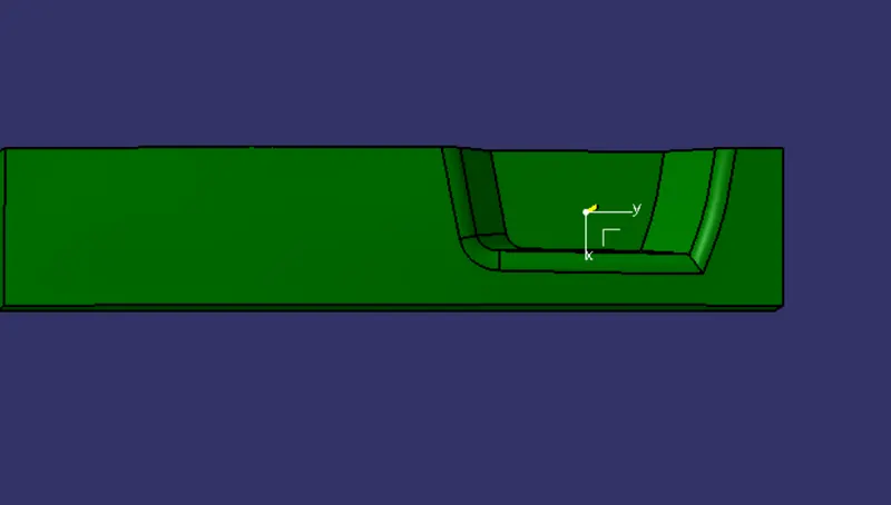
Isometric view
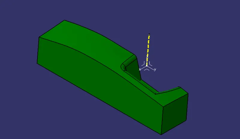
Output
Conclusion
I have successfully designed the Core&Cavity for the Swith bezel, and gained lot of knowledge about Core&Cavity design