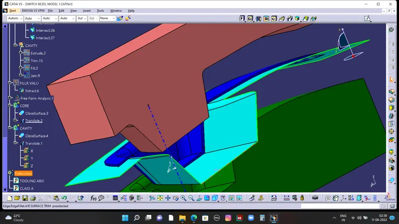
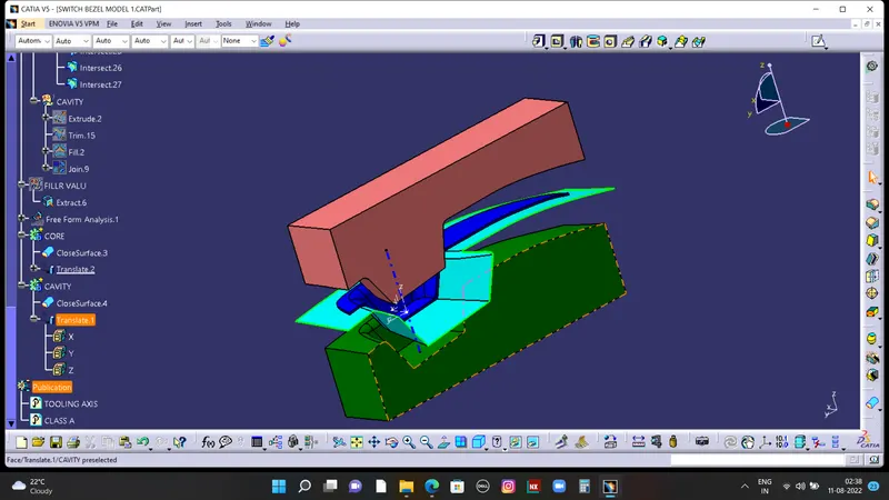
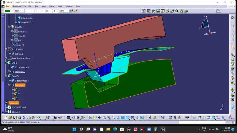
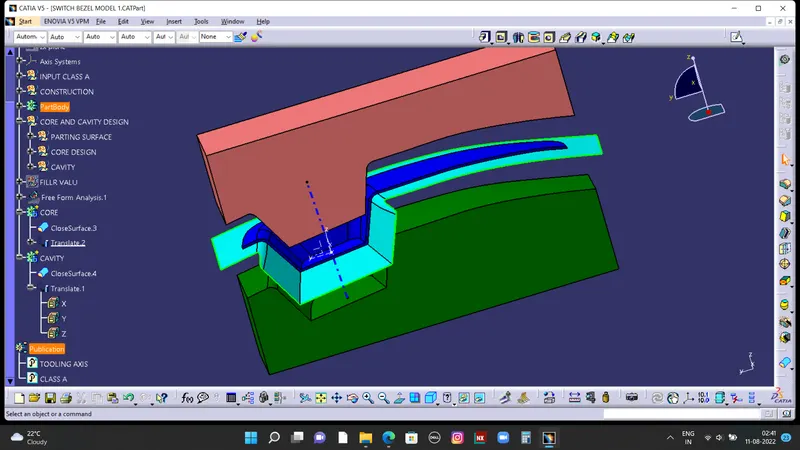
PROJECT 15 - CATIA V5 - CORE & CAVITY DESIGN FOR AUTOMOTIVE TRIMS MOULDING.
AIM:to create the core and cavity for the switch bezel condering the all design rules.
TOOLING AXIS:
IT IS THE AXIS IN WHICH THE DIRECTION CORE AND CAVITY OPEN. THIS IS THE VERY IMPORTANT
FOR PRODUCTION OF PLASTIC COMPONENT. MOST OF THE DEFECT WILL DONE IMPROPER
TOOLING AXIS CREATION BY THE PLASTI DESIGNER.
THERE ARE SO MANY METHODS FOR CREATION OF TOOLING AXIS. INTERSECT IS THE ONE OF THE
METHOD FOR CREATING THE TOOLING AXIS.
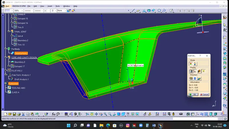
BYSECT METHOD:
FOR DOING THIS YOU SHOUD FIND OUT THE WHAT IS THE BEST TOOLING DIRECTION. FOE DOING
THAT TO ROTATE THE PART AND SEE ALL DIRECTIONS AND CHOOSE THE WHICH DIRECTION WILL
BE COMFORTABL
THEN CREATE THE POINT ON THE BASE MOSTLY CREATE THE POINT WHERE THE HOLE OR POCKET
ARE GIVEN. AND AFTER THAT INSERT TOOLING AXIS IN THAT POINT.THEN FIRST SEE IN X DIRECTIO
IT ILL CLEAR THE ALL FACES OF PARTS IF NOT CREATE A PLANE AND INTERSECT TO EACH OTHER.
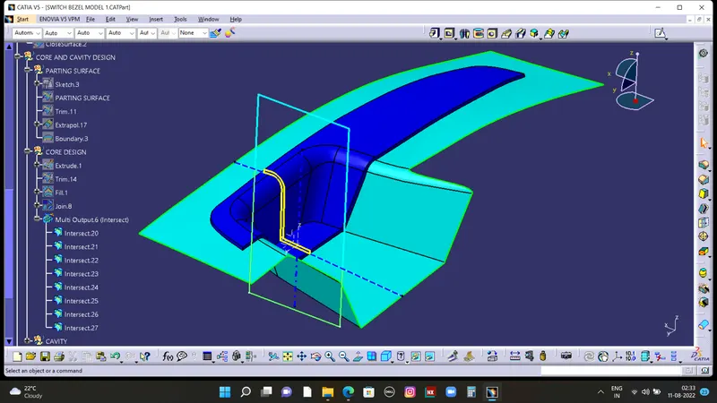
THE FALLOWING WINDOW WILL BE APPEARED.
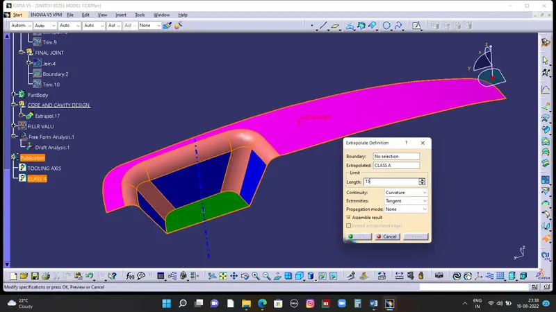
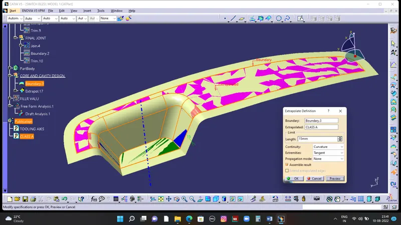
THE CREATE THE MEAN LINE. AND GO TO Y DIRECTION AND DO THE SAME PROCESS WE ARE DON
IN X DIRECTION.
THEN BYSECT THESE ALL LINES TO GET THE MAIN TOOLING AXIS. THIS TOOLING AXIS CAN BE
CLEARED ALL FACES OF THE PART.
DRAFT ANALYSIS:
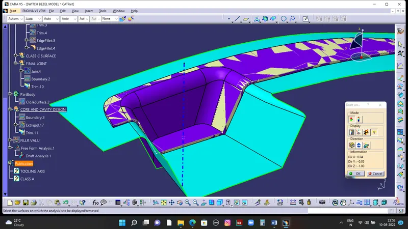
THE PURPOSE OF DRFT ANALYSIS IS TO DETECT THE PARTSHOULD BE EAISILY WITHDRAWL FROM
THE CORE AND CAVITY BY USIN OF DIFFRENT COLOUR RANGES.
THIS ANALYSIS WILL BE DONE BY DRAFT ANALYSIS COMMAND. FOR THIS COMMAND GO TO
INSERT< ANALYSIS< FEATURE DRAFT ANALYSIS
THESE ARE THE FALLOWING STEPS TO DO THE DRAFT ANALYSIS ON SWITCH BEZEL.FIRST TO CLICK
THE DRAFT ANALYSIS COMMAND THE FALLOWING WINDOW WILL BE APPEARED.
AND THEN CHANGE INTO MATERIAL MODE
THEN CLICK THE COMPASS AND DRAG ON THE TOOLING AXIS. AND THEN CLICK ON THE PART
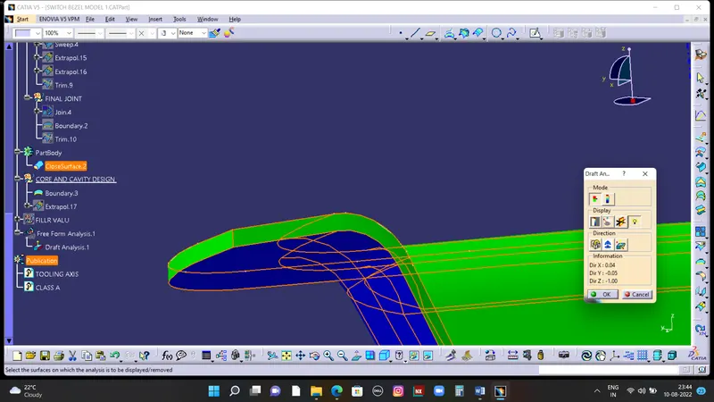
THEN THE COLOUR WILL CHANGES OF THE PART.AND YOU CAN CHANGE THE VALUE USING SCAL
OPTION.AND ALSO A RUNNINNG PINT COMMAND USED TO FINDOUT THEANGLE OF PART FROM
THE TOOLING AXIS.SO YOU CAN MODIFY THE TOOLING AXIS BY USING COMPASS TO GET PROPER
RESULTS.
WE CHECKED DRAFT ANALYSIS REPORT FOR SOLID BODY & DRAFT ANALYSIS REPORT FOR CLASS A
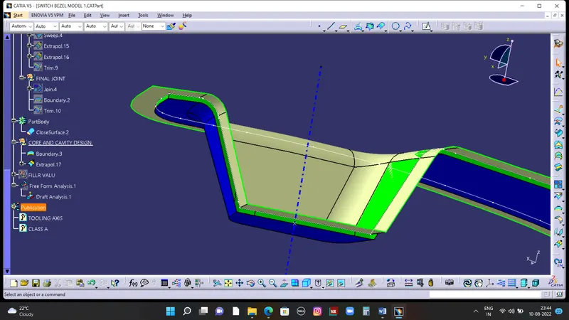
CORE AND CAVITY design for switch bezel:
first of all you have full knowedge about waht is , cavity, parting surface, parting line etc
core and cavity:
a core is the one part of the mould.and it is respponsible for half of the molded part.
actually core is the projection of the bodyand cavity is the depression of the body. these core and cavity combines to form a mould. then the plastic material injected into these
mould to get a plastic part.
parting surface:
injection mold has two major components one is core and another is cavity .during the
injecction molding process, these two halves are pressed tightly from a sealed hollow to
avoid the melt flow leakage and maintain certain holding pressure, the pressed surface ar
called parting surface , usually parting surface are the biggest projection outline of the
part
parting line:
it is the area in which parting surface and component meets Or it is a junction between
core and cavity
and the parting surface has some set of rules because the product quality mostly depend
on the parting surface.
DESIGN PARTING SURFACE SHOULD FOLLOW THE FOLLOWING PRINCIPLES :
Design the injection mold simple as possible .Avoid or reduce side parting as much as
possible to reduce complexity of the mold making.
Ease of de-molding as far as possible, for instance the plastic parts should stay in fixed
halve of injection mold and should ejected by ejection system avoid , side de-molding
action,
Ensure the dimension accuracy of the molded parts ,Try to make the parts similar
dimension accuarcy reqirements in same mold to reduce manufacturing and assembly
errors .
Ensure apperance reqirement of molded parts,finish or mismatch usually occurs on partin
surface , so the parting surface should not be designed on high quality requiremnent
surfaces.
Ensure adequate venting.If possible parting surface should be place at the end of the mold
flow.This is going to be advantage of fillng and venting.
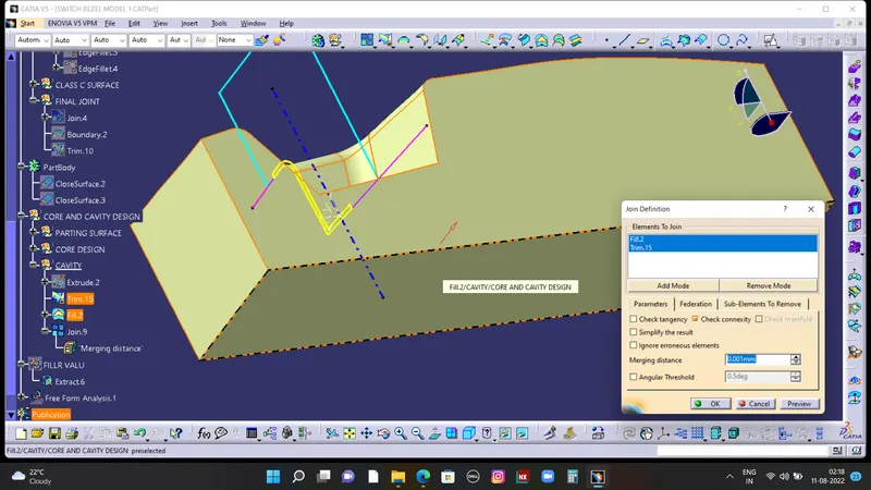
core design:
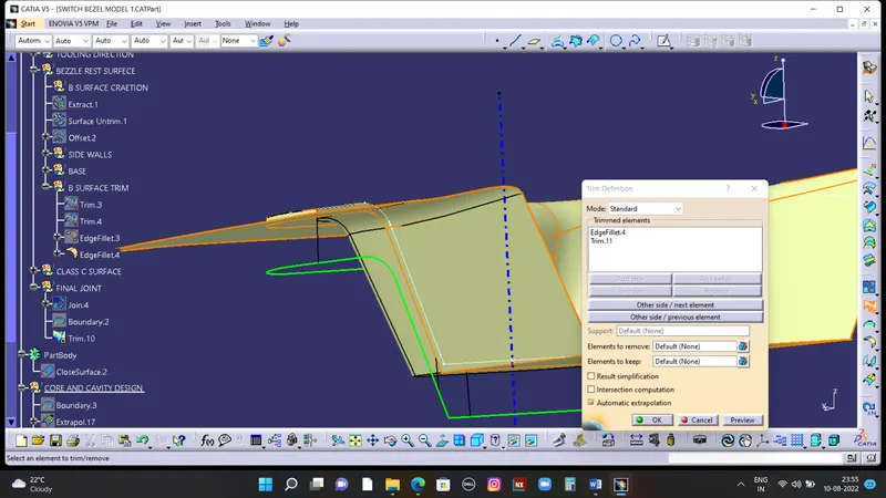
To etrapolate class A surface
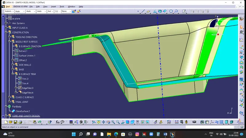
trim class A with class c to get inside portion
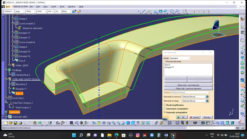
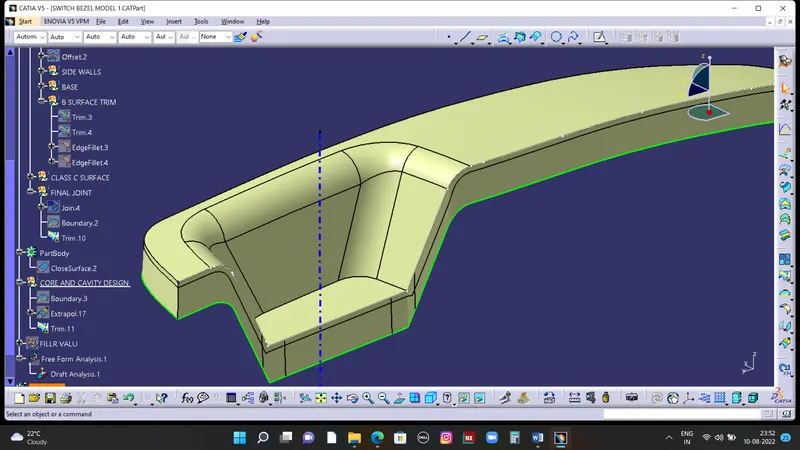
Now, trim the B surface with with output of Class A & C that will be parting surface with
resprect to area.Extrude the skectch overall throgh the tooling direction are trim it with
parting surface
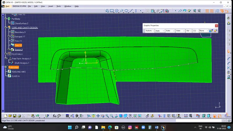
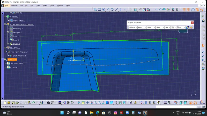
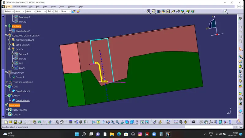
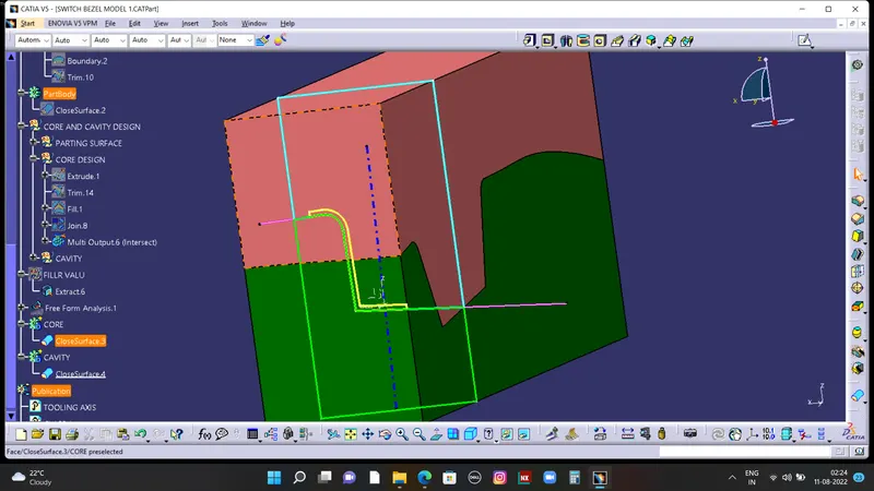
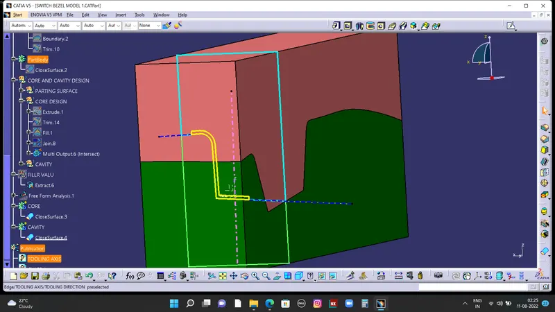
Final output of core design
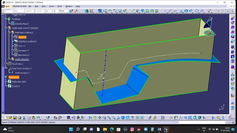
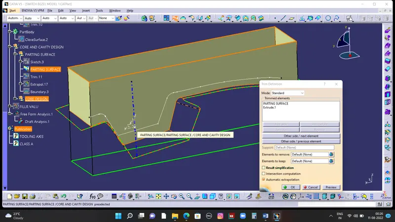
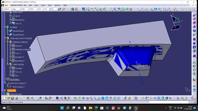
part body of core
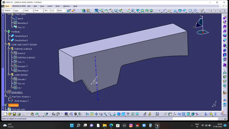
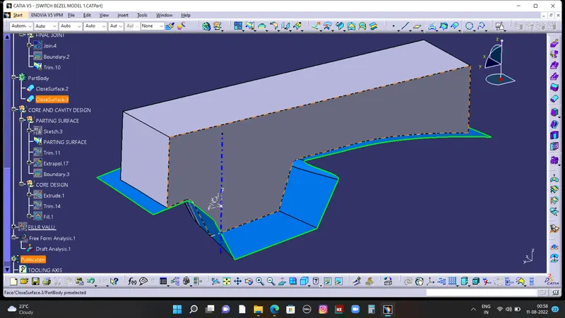
Similarlly,Repeating the same as done for the cavity part and trim it on other side surface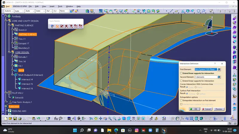
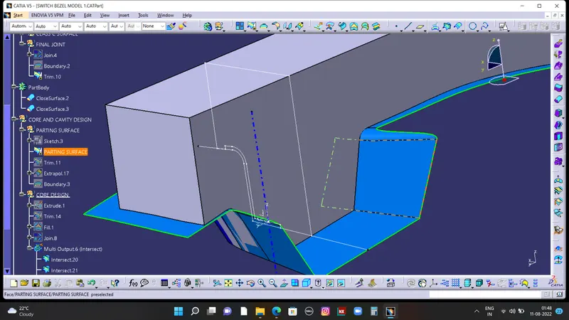
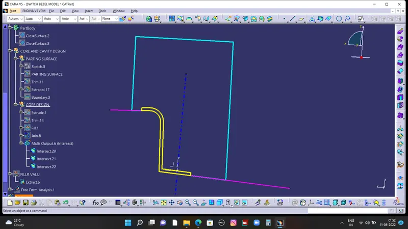
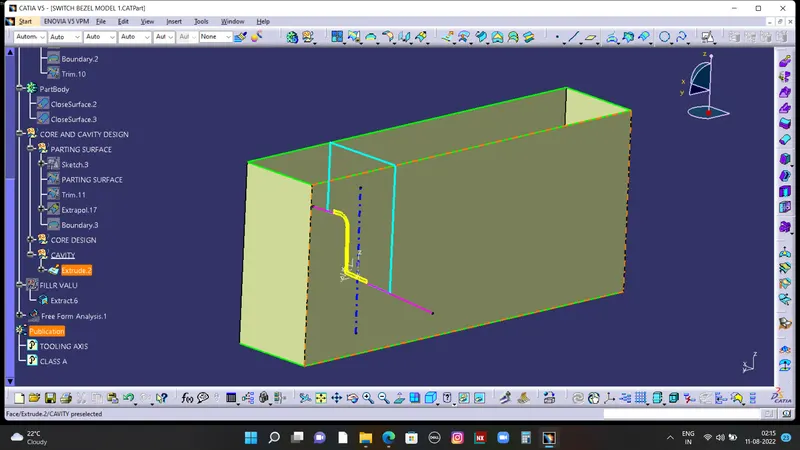
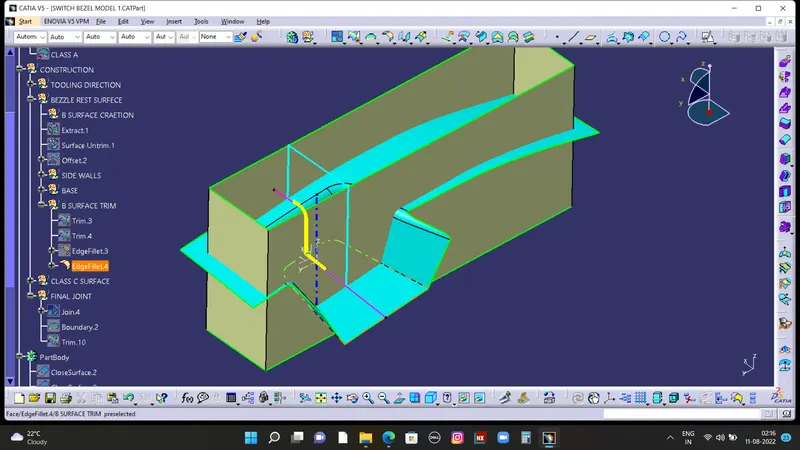
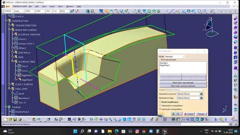
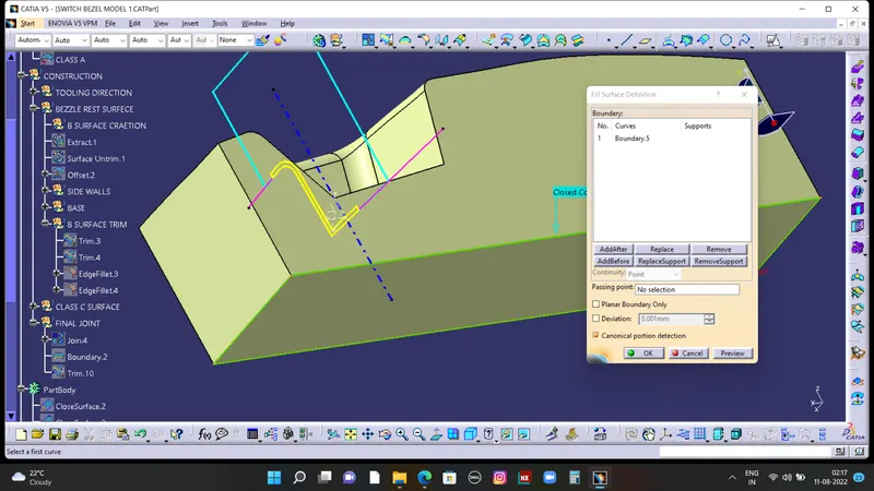
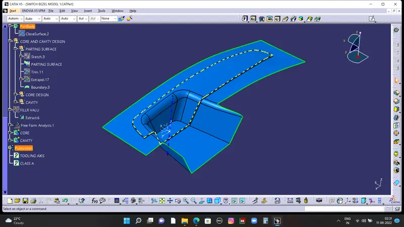
parting surface and parting line
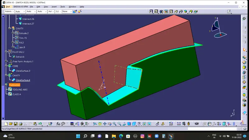
FINAL Close body surfaces of Core & cavity are,