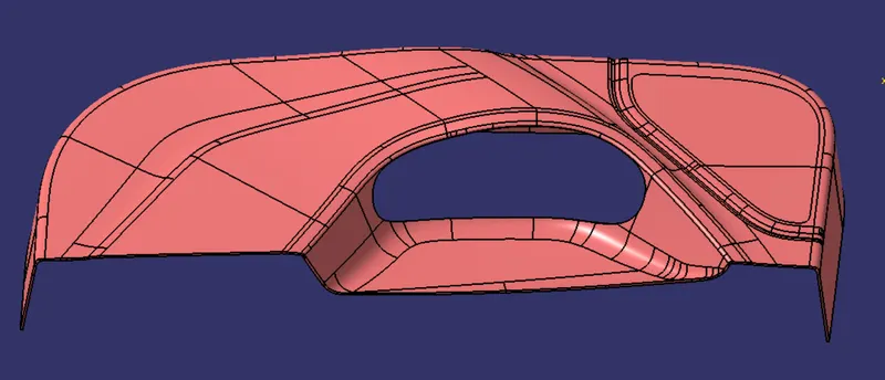
Week 8 - Challenge 5 - Door Trim Lower
Aim:
- To Create the Door Trim Plastic component through the given Class-A surface. To begin with, the tooling axis for the given Class-A Surface should be created meeting the requirements of the draft angle and at the end perform the Draft analysis on the model
Class A Surface:
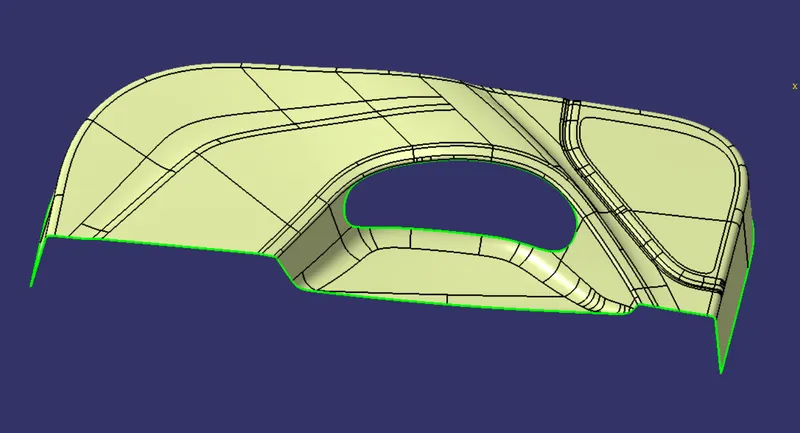
- After receiving the clasa A surface check the connectivity of the surface using join or by boundary.
- If it is not join together make it with a minimum tolerance of 0.001 to 0.003 and check for connectivity of the surface.
Tooling Axis:
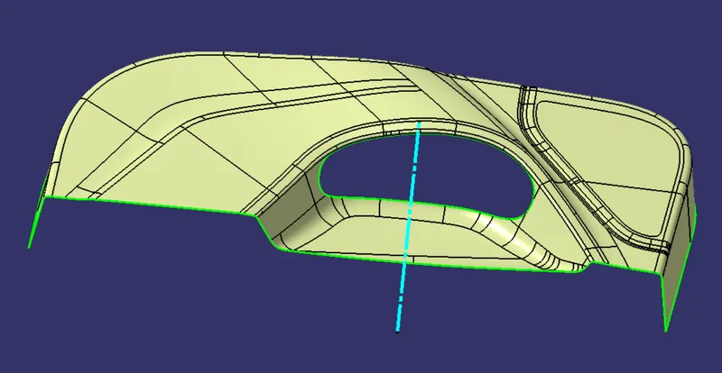
- The direction in which the mould open and closes is called the tooling axis direction.
- Tooling Axis can be created by three methods, they are as follows
1.Bisecting method
2.Normal to surface
3.Point on Direction
- Here in DoorTrim challenge point on direction method has been used to draw Tooling Axis.
- By taking the flat surface of the Door Trim and extract the surface and create the center point and using point on direction method line is drawn along the Y-Axis.
- Thus, the Tooling Axis Created.
Draft Analysis:
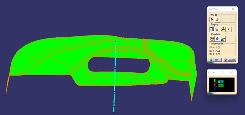
- The Draft Analysis command enables you to detect if the part you drafted will be easily removed. This type of analysis is performed based on color ranges identifying zones on the analyzed element where the deviation from the draft direction at any point, corresponds to specified values.
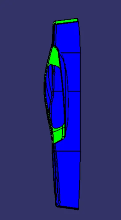
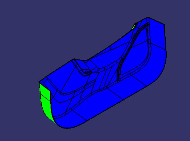
- The colour scale on the bottom visualizes, whether the draft angle meets the requirements or not (3 deg) by indicating the colours Green, Blue and Red. We need to align and fix the compass to the tooling axis then the draft angle analysis will be checked out.
Draft Analysis on the Class A Surface:
Class B Surface:
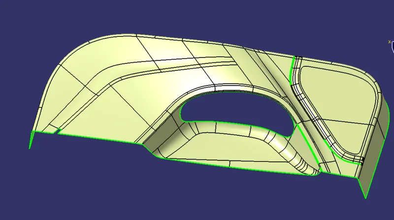
Class B surface with patches
- Here Class B surface is created by offesting the Class A surface by 2.5mm(according to thickness).
- After offesting the surface some patches are found in the surface.
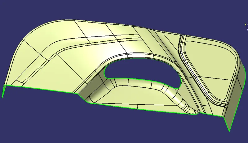
Class B Surface
- By using commands like extract, Extrapolate and trim commands patches has been removed and a complete surface has been created.
Class C Surface:
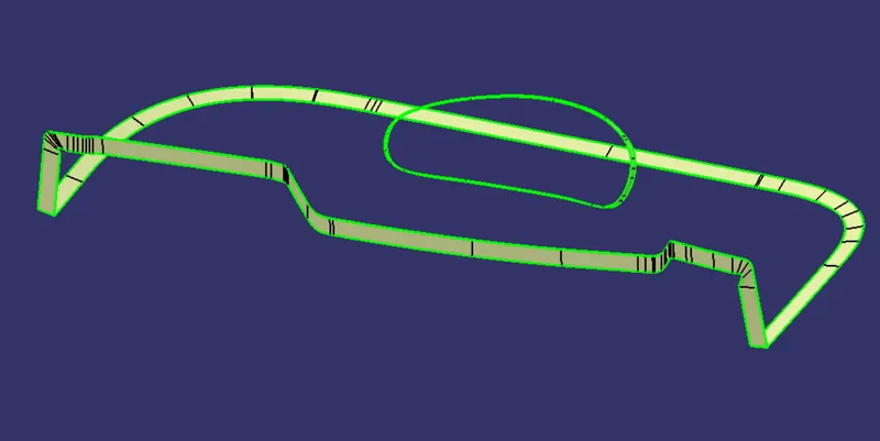
- By taking the boundary of the Class A surface and by using the sweep (reference by surface and with draft direction) method Class C Surface is created.
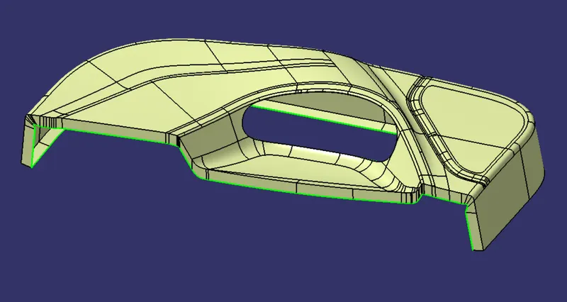
- By using Join command Class A surface and Class C are joined.
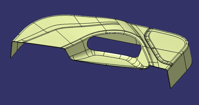
- By Trimming the Class AC surface with B surface the final surface has been created.
Screenshots of the solid model with the proper color code of the draft angle in various orientations:
Front View:
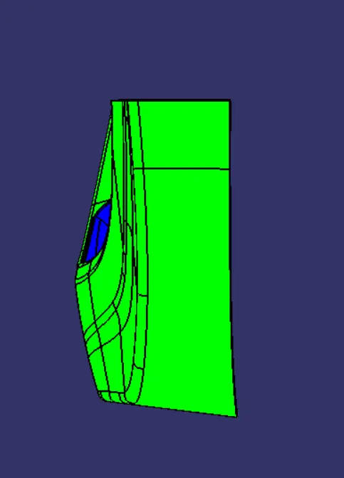
SideView:
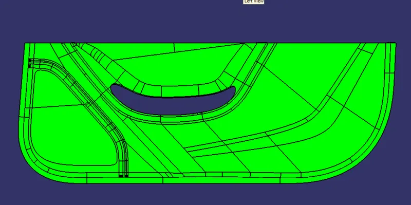
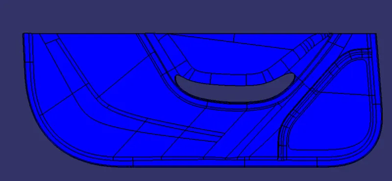
TopView:
Isometric View:
Final Solid Body: