Week 8 - Challenge 5 - Core & Cavity Design
WEEK 8 CHALLENGE-CORE AND CAVITY DESIGN OF SWITCH BEZEL
AIM :
To perform draft analysis for the given class A surface and make a surface model then close the volume with the body and again check the draft analysis there after design of core and cavity for the model should be done.
PROCEDURE :
DRAFT ANALYSIS :
No parts can be ejected from the tool if it is having a straight 90 degree profile from its base surface. A small draft angle is provided to each and every area of the component in order to get an easy removal of the component from the tool. Draft analysis technique is used to analyze whether our part model created in cad is manufacturable based on the draft condition applied. Here the part should get easily removed from the panel dies (in case of Sheet metal part) or Mold (in case of plastic).
Here we are providing a direction in which components should eject inorder to get an easy removal of components from the tool. In other words it also lets us know whether the model is having a draft angle and how much is the draft angle from the tool direction.
TOOLING AXIS :
The tool axis is the parameter which decides whether the tool enters into mould or not as as it denotes the draft clearance angle where a moulded part is easily removed from the mould.
PROCEDURE FOR CREATING TOOL AXIS :
Firstly we will be given with a class A surface which is looked as a asthetic and a smooth finish which is created with a Alias software workbench which is also known as a free imagination surface.
For that class A surface we need to check a boundaries first to check any unattached faces is present in
that surface.
The below is the image of a class A surface which is given as a input:
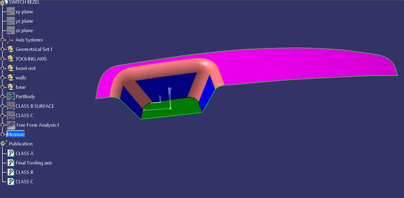
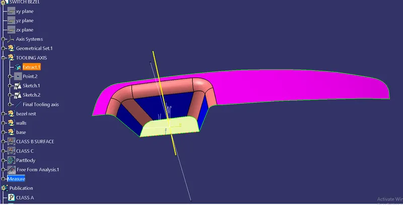
- So next we need to take a dummy tool axis to get a real tool axis.
- Next we take inclined lines to the surfaces we assume that draft is required.
- Then we intersect the both the lines and the bisecting line will be the tooling axis.
- Below is the image of the tooling axis.
DRAFT ANALYSIS PROCEDURE :
Change the view mode to Customize View Parameters and select Material option from the view mode.
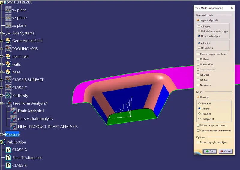
Next we need to get the compass and place it on the tooling axis.
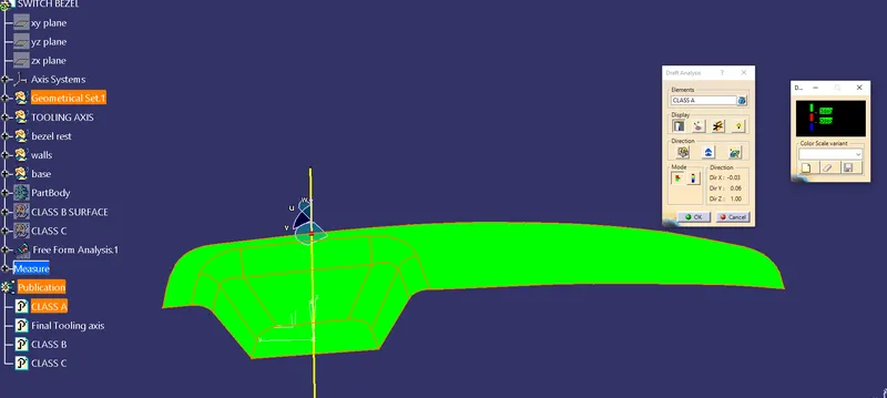
Insert > Analysis > Draft Analysis
- Draft Analysis dialog box with colour scale (with quick analysis mode) appears on the screen. So the first mode option is the quick analysis mode and second is full analysis mode. Here the quick analysis mode is used.
- Change the value of green according to the draft angle provided to the part.
- To get a clear picture, either we need to adjust the compass by holding the marked region of compass and dragging it towards the opposite direction or by selecting the inverses draft direction option inside the direction of Draft Analysis.
- After getting green colour on the component, try to adjust the compass using the knob, and adjust the direction of the compass to get green on the entire top panel region.
- Try zoom in and check if each and every region of the panel is showing green, if in some region, red or blue is showing instead of green.
- If any errors is present try to adjust the compass direction to optimise the errors.
- If any error is unable to change we need to use the side cores for that positions.
SURFACE MODEL CREATION:
- So from the class A surface we need to get the extracts and offset them to get the exact replica of the class A surface.
- Below are the images of the surface model creation.
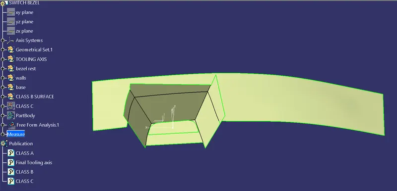
So after the offset is done trim operation is done to get the class B surface
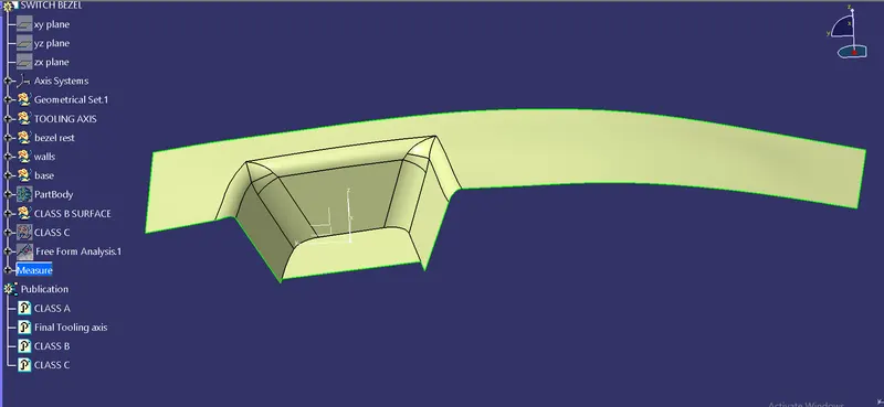
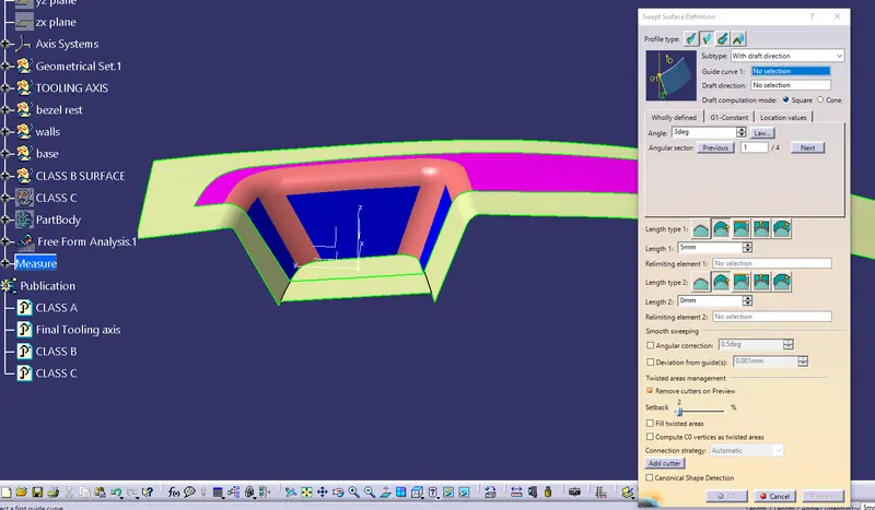
So now to get the class C surface we net to do a Sweep operation for class A surface and we need to do trim for both of them to get a class C surface.
The below is the image of class C surface after sweep and trim operation.
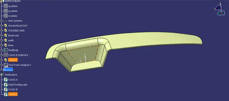
Now after creating a closed surface we need to give a body for that closed surface using closed volume tool in the part workbench.
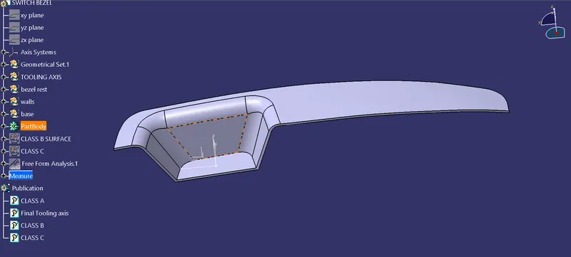
So now we need to check the draft again to conform the part for manufacturing which is class D.
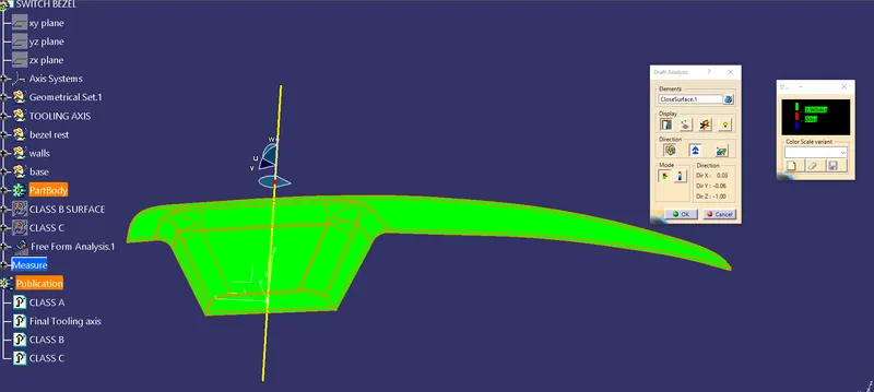
The value at which the draft angle is cleared at 2.965 degrees.
So now we need to design the core and cavity blocks for the part body which is drawn from the hollow surface model.
CORE DESIGN :
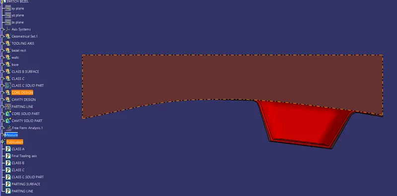
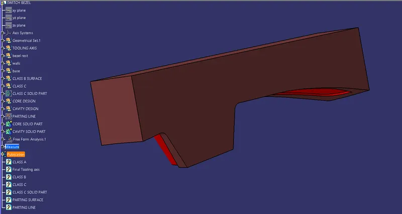
First we are going to design the core part from the class B and class C trims so that we get the core block which consists of the mold impression.
Below are the images for the trims of class B and class C :
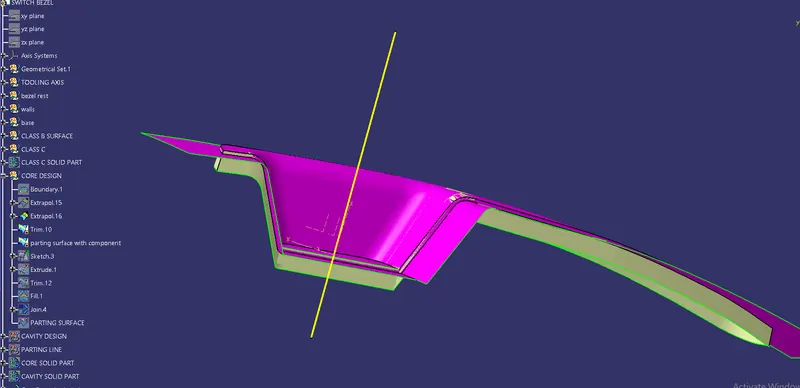
Now we create a sketch on top of the surface and we extrude the sketch to trim the previous trim to get the core surface model and then we fill and join the top surface of core which has opening.
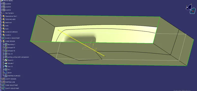
Now we trim it to get the core surface model and below image is shown for the same.
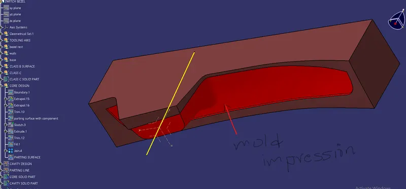
Then we should draw the shell into solid part from the part workbench.
FRONT VIEW :
TOP VIEW :
ISOMETRIC VIEW :
CAVITY DESIGN :
Now we need to design the cavity block where core projection should insert into the cavity block.
From the same sketch we extrude it and trim it with the B surface and then fill the opening and join the whole surface model which gives the cavity block.
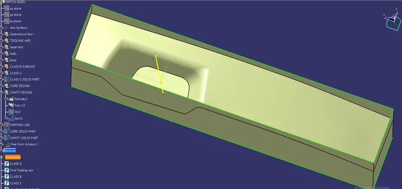
The cavity block for the model is shown below.
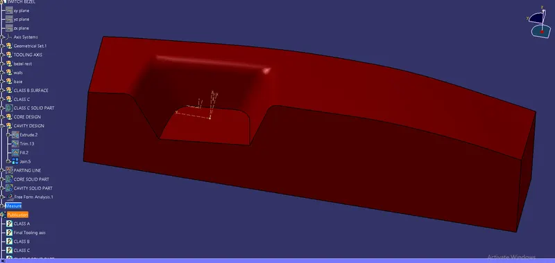
Now this shell also should be filled with solid to create a solid part.
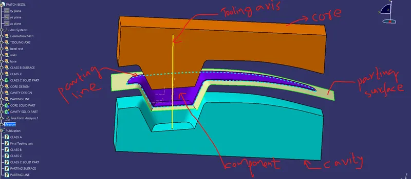
Now the parting line and the parting surface will play a major in core and cavity design because by having a parting surface on the B-surface if any flash is occured it can be removed from the B-side as it is less considered by the customer otherthan this if the parting surface is on the A-surface it results in the damage to class-A surface which is not preferred by the customer.
FRONT VIEW :
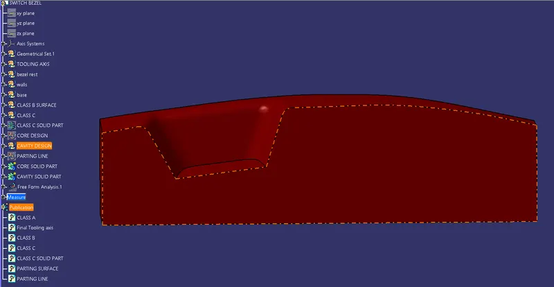
TOP VIEW :
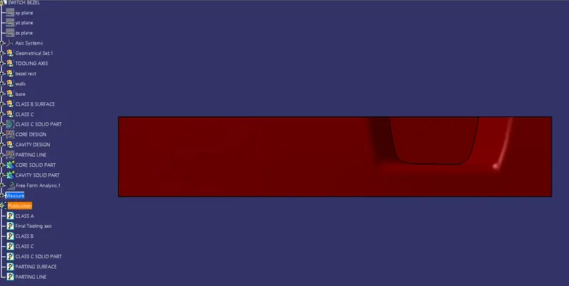
ISOMETRIC VIEW :
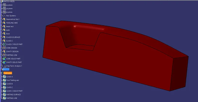
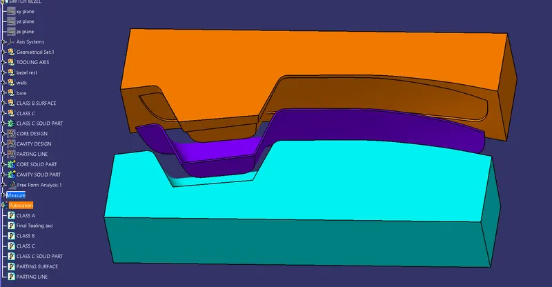
Below are the images for the core, cavity, mold, parting line and parting surface. :
CONCLUSION :
At finally we consider where the molten liquid will be going to fill in core or cavity and always preferred that parting surface will be located on the B-surface.
GOOGLE DRIVE LINK :