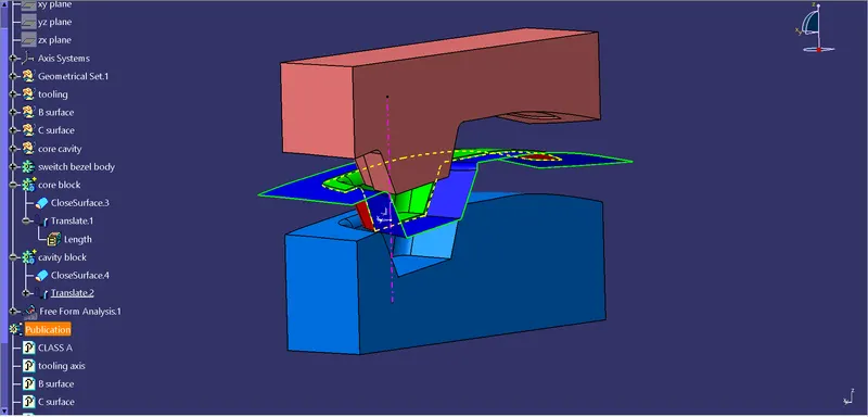
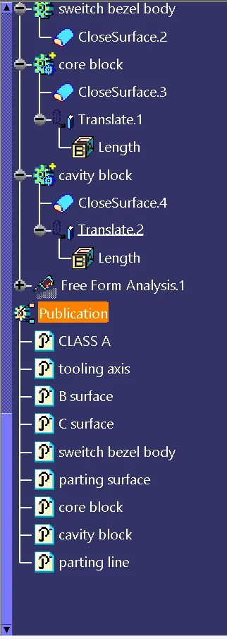
Week 8 - Challenge 5 - Core & Cavity Design
Creating the core and cavity blocks for the switch bezel:
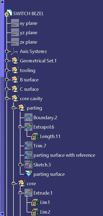
Creating the parting surface:
The boundary line of the A surface is taken and extrapolated. It is then trimed with the sweep done to close the C surface.
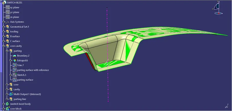
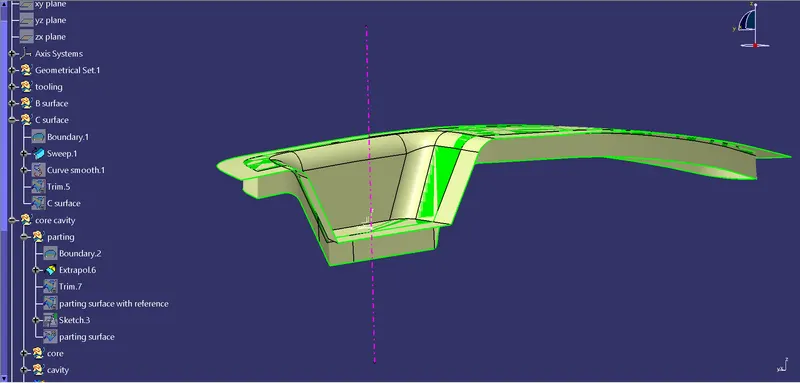
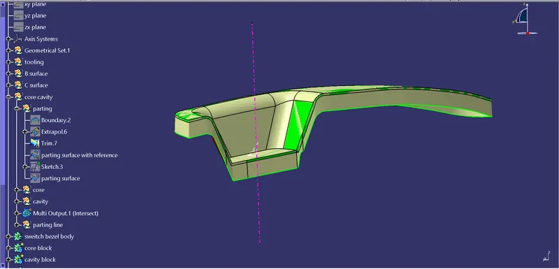
Then it is trimed with the B surface in a way where the model sets inside the surface.
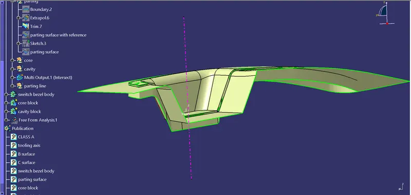
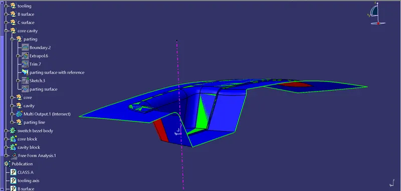
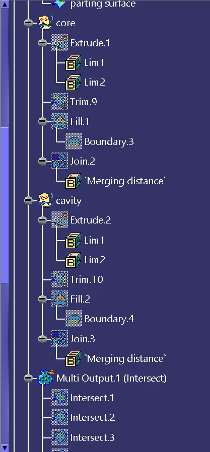
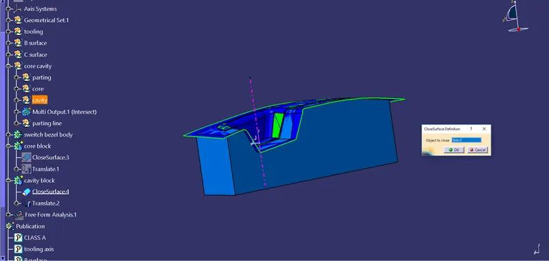
Creating core and cavity blocks:
To create the blocks, First a rectangular sketch is created with a mesurement where the model lies inside it.
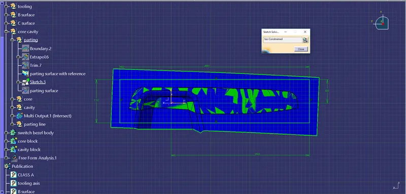
Then this sketch is extruded to some length.
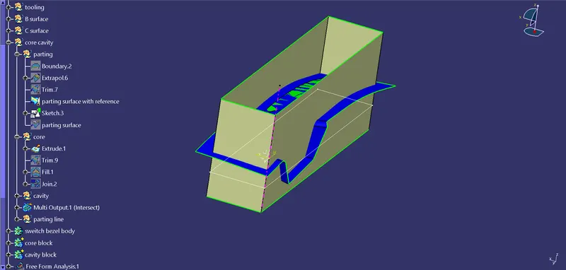
It is then trimes with the parting surface and the other side is filled and joined to form a closed surface.
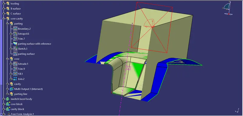
It is then filled with solid and the core block is made.
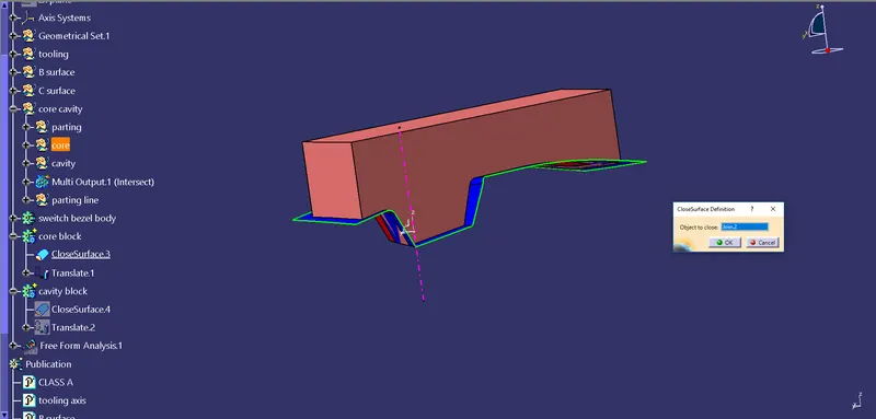
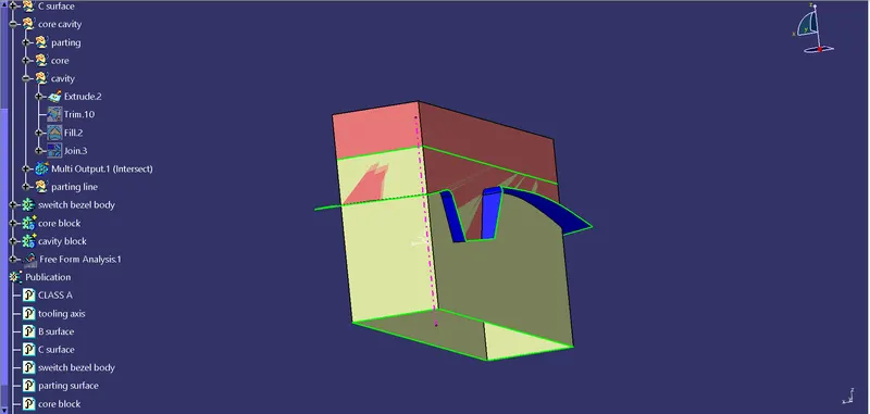
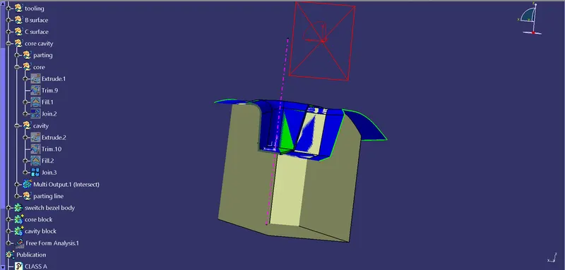
The sketch is then again extruded to a length in opposite direction, and the same procedure is done to form the cavity block.
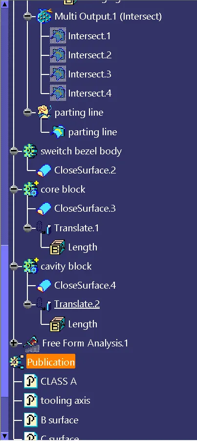
Creating the parting line:
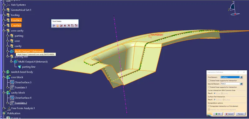
The B surface is intersected with a stage surface called trim 5 which is the combination of class A surface and the sweep to close in C surface to form the parting line.
Creating parting surface with component space:
The parting surface created first is now again trimed with the parting line, so that the parting surface will be clear.
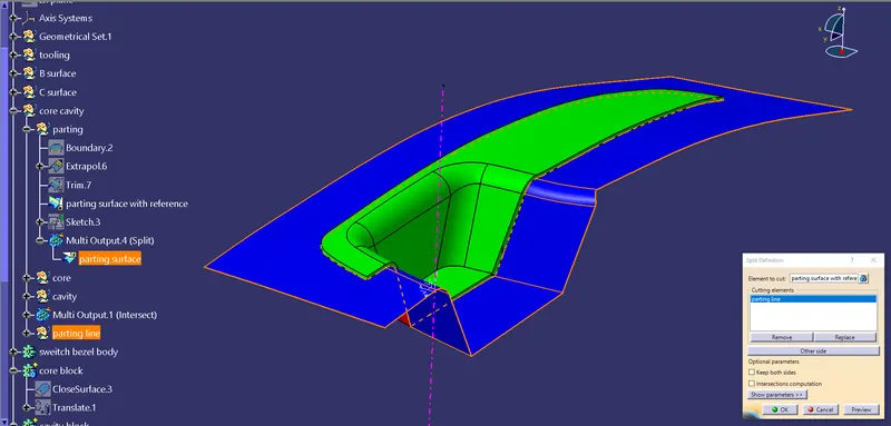
Then the Core and Cavity blocks are translated in the direction of the tooling axis to a 50mm, so that wwe can have a good look at it clearly.