Week 8 - Challenge 5 - Core & Cavity Design
Aim: Design of core & cavity of switch panel bezel.
SOLUTION:
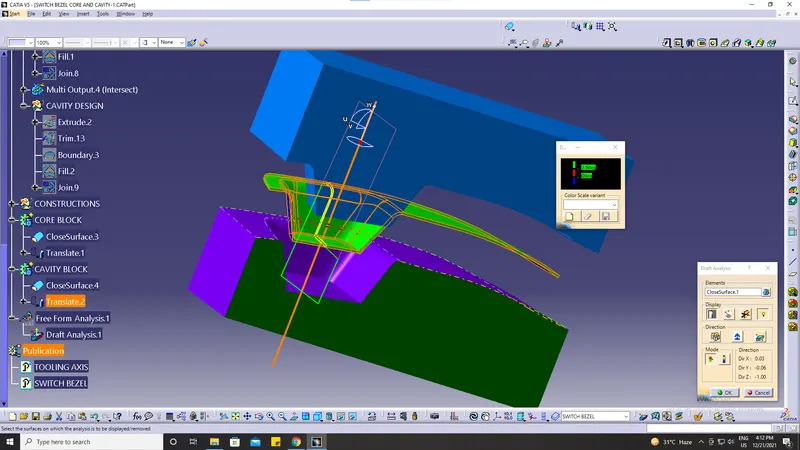
Draft analysis: The Draft Analysis command enables you to detect if the part you drafted will be easily removed. This type of analysis is
performed based on color ranges identifying zones on the analyzed element where the deviation from the draft direction at any
point corresponds to specified values.
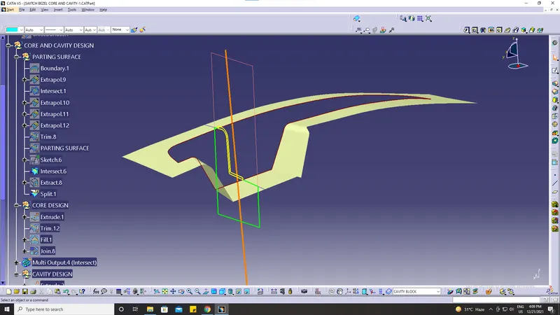
PARTING SURFACE:
Generally, injection mold has two major components: the movable halves and the fixed halve, during the injection molding process, these two
halves are pressed tightly from a sealed hollow to avoid that melt flow leakage and maintain certain holding pressure, the pressed surface is
called parting surface, usually parting surface is the biggest projection outline of the part.
Parting surface design principles
Parting B surface design directly affects the product quality, ease of construction, and operation of the injection mold, the mold design is one
of the key factors to success.
DESIGN PARTING SURFACE SHOULD FOLLOW THE FOLLOWING PRINCIPLES:
1. Design the injection mold sample as possible. Avoid or reduce slider parting as much as possible to reduce the complexity of mold making.
2. Ease of de-molding as far as possible, for instance, the plastic parts should stay in a fixed halve of the injection mold and should be ejected by the ejection
system avoid, side demolding action
3. Ensure the dimension accuracy of the molded parts. Try to make the parts similar dimension accuracy requirements in the same mold to reduce
manufacturing and assembly errors.
4. Ensure appearance requirement of molded parts, finish or mismatch usually occurs on the parting surface, so the parting surface should not be
designed on high-quality requirement surfaces.
5. Ensure adequate venting. If possible parting surface should be placed at the end of the mold flow. This going to be the advantage of filing and
venting.
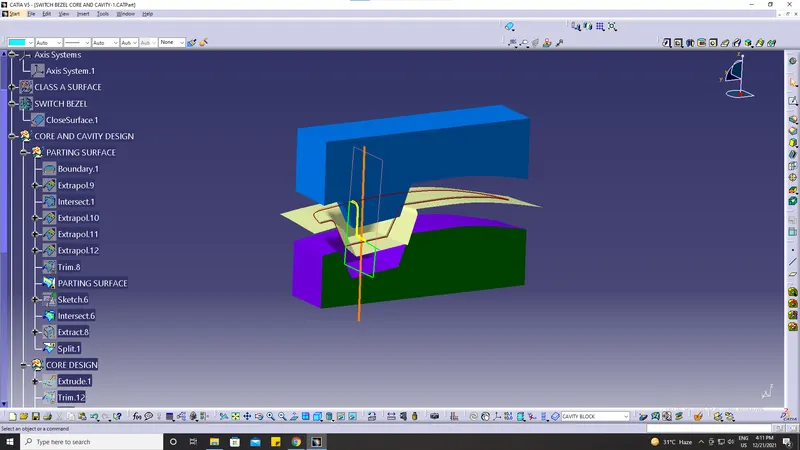
Design of core in step by step explanation in image portion.
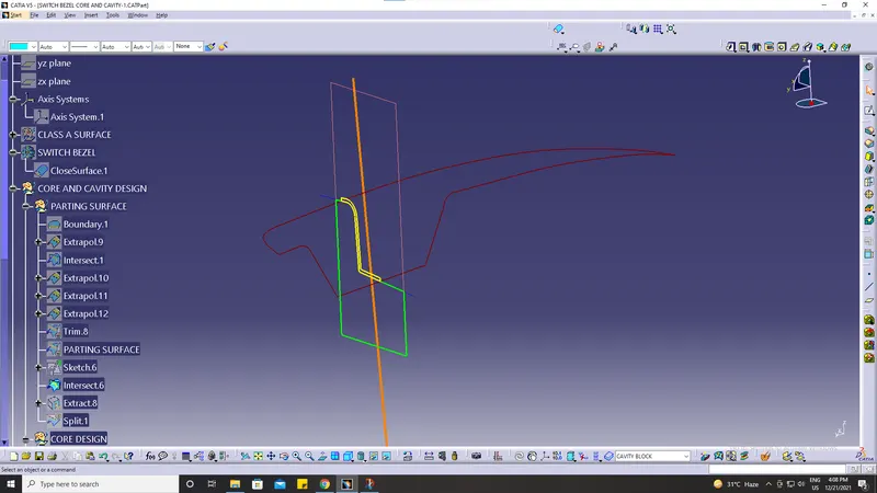
First, we select a boundary of the class A surface.
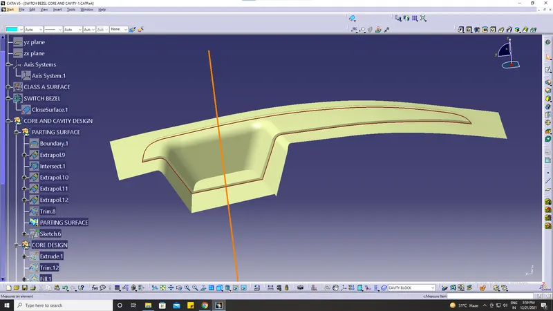
Then extrapolate with 11 mm.
Now, have a sketch on XY plane as shown in the below image
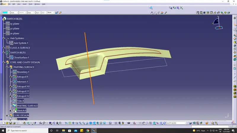
Extrude the sketch overall to the tooling direction are trim it with a parting surface.
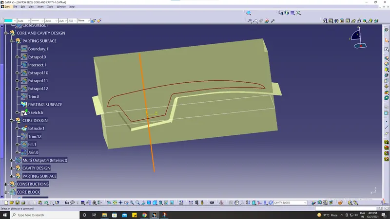
then fill the upper surface & then make a close body
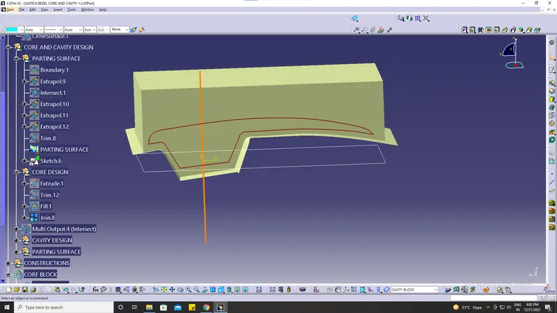
CUT SECTION:
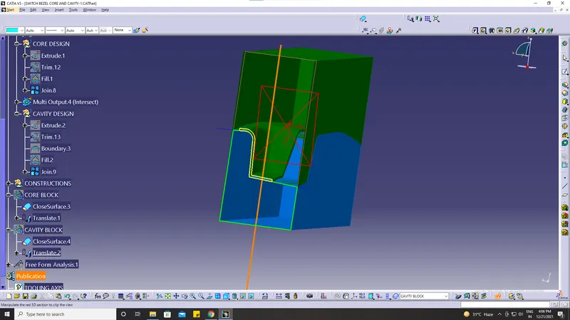
Now check the intersection
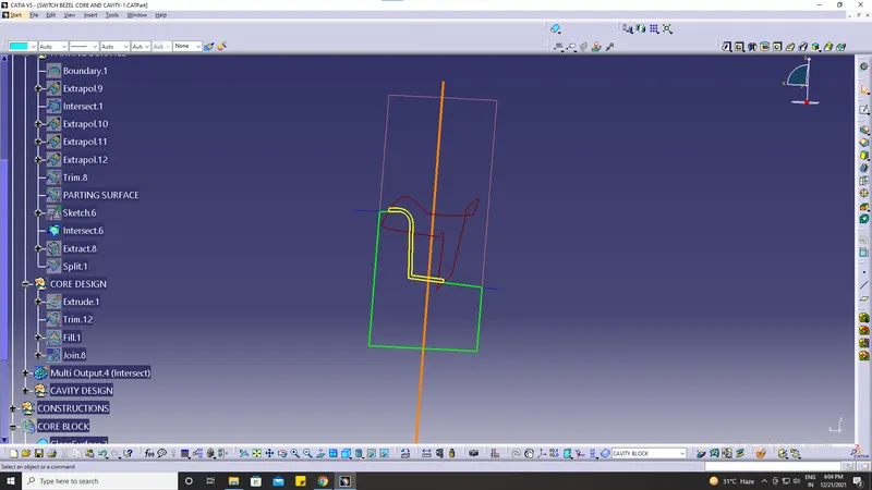
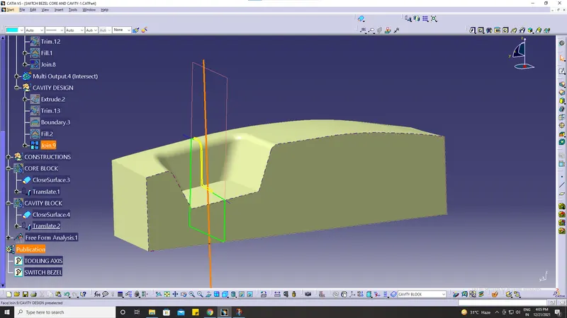
similarly repeating the same as done for the cavity part & trimming it on another side surface.
PARTING LINE:
PARTING SURFACE:
NOW TRANSLATE BOTH CORE AND CAVITY:
DRAFT ANALYSIS:
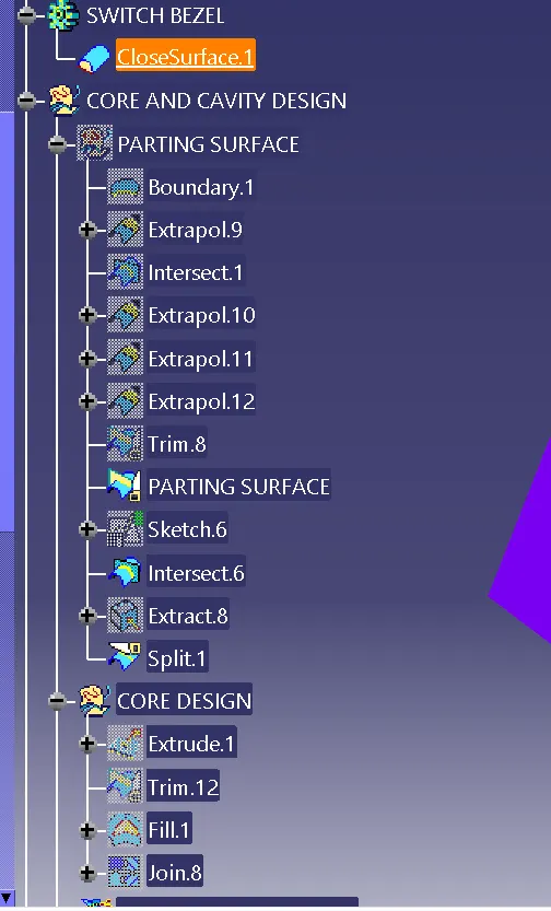
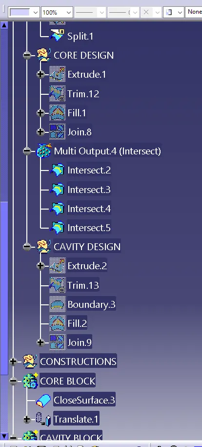
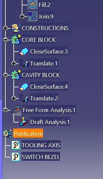
TREE STRUCTURE: