Week -2
AIM 1: Make a Simulink model of Doorbell using solenoid block with the following details:
In the above arrangement, when the switch is closed the electromagnet receives electrical power from the battery and pulls the metal arm to hit the bell producing sound.
Create a situation where the switch is closed for 2 seconds and then released. Observe the physical movement of the plunger.
SOLUTION:
SOLENOID: A solenoid is a type of electromagnet, the purpose of which is to generate a controlled magnetic field through a coil wound into a tightly packed helix. The coil can be arranged to produce a uniform magnetic field in a volume of space when an electric current is passed through it.
Basic components used to generate a simple doorbell circuit are:
1. Battery
2. Switch
3. Solenoid
4. A bell with plunger
BLOCK DIAGRAM:
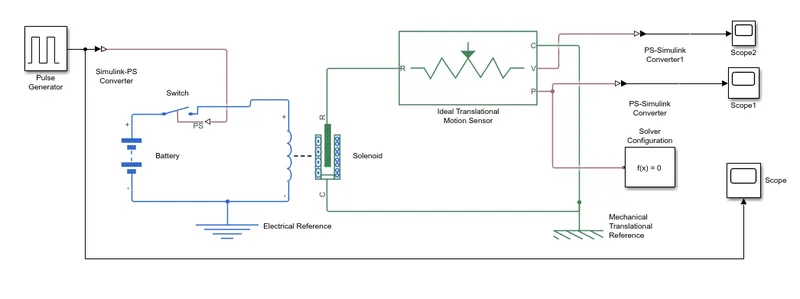
EXPLANATION:
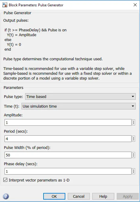
1. An input signal is Amplitude = 1, Period = 4sec Pulse Width = 50%, Phase delay = 1.
2. Battery is connected to the solenoid via switch. when the pulse generator creates an input signal its closes the switch and
allow the current to flow into the solenoid.
3. The plunger part of solenoid is connected to the motion sensor to get the appropriate output of the position of the plunger. A
mechanical translation reference is provided for the circuit.
4. The scope is connected to view the output from the motion sensor.
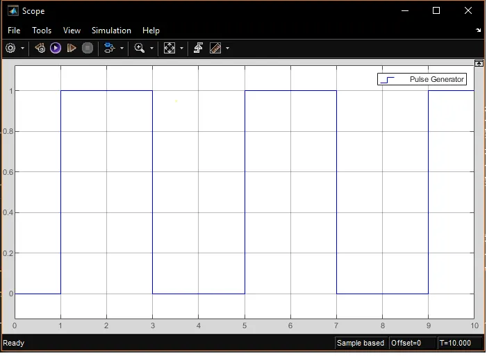
RESULT:
TIME VS AMPLITUDE
TIME VS POSITION:
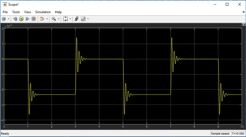
When the pulse generator amplitude is 1 , there is a movement of the plunger and when the amplitude returns to 0 the plunger
moves to the original position. Due to low damping value it undergoes several oscillations before coming to the original position.
AIM 2: Use a thermistor to sense the temperature of a heater & turn on or turn off the fan as per below conditions:
Temperature source: 20 °C from 0 to 10 seconds, 27 °C from 10 to 30 seconds, 23 °C from 30 to 50 seconds
Fan conditions: ON if the temperature above 25 °C, OFF otherwise
SOLUTION:
THERMISTOR: A thermistor is a type of resistor whose resistance is strongly dependent on temperature, more so than in standard resistors. The word is a combination of thermal and resistor. In PTC thermistor when temperature increases, the resistance increases, and when temperature decreases, resistance decreases. This type of thermistor is generally used as a fuse and in NTC thermistor when temperature increases, the resistance decreases, and when temperature decreases, resistance increases.
Basic components used to generate a simple cooling fan circuit are:
1. Battery
2. Thermistor
3. Fan
4. Transistor
5. Resistor
BLOCK DIAGRAM:
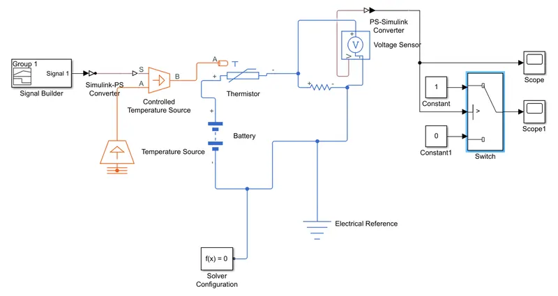
EXPLANATION:
1. A signal builder block is used to achieve the given temperature source (20 °C from 0 to 10 seconds, 27 °C from 10 to 30
seconds, 23 °C from 30 to 50 seconds)
2. Controlled Tempearature Source is an ideal energy source in a thermal network that can maintain a controlled temperature
difference regardless of heat flow.
3. A NTC thermistor is used to sense the tempearature change .A reference resistor is used in series to measure the voltage drop
change as temperature change.
4. Voltage sensor is used to measure the voltage drop and generate an output signal given to the logic circuit to turn on/off the
fan.
change the temperature source to 293k to get results.
SIGNAL BUILDER BLOCK
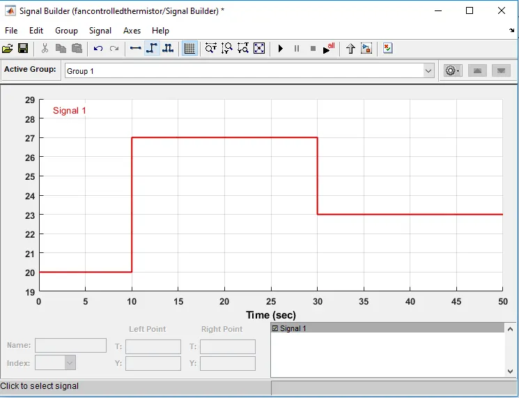
Change the values of signal builder block from right side of the graph. By double click on the point we can change the points as specified in the question.
RESULT:
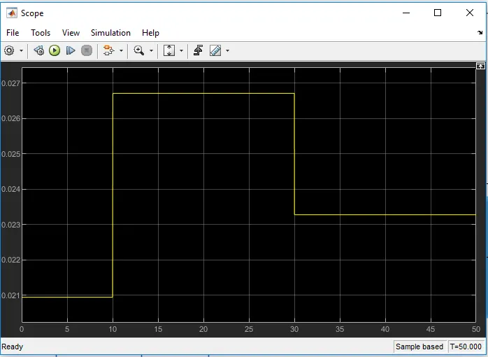
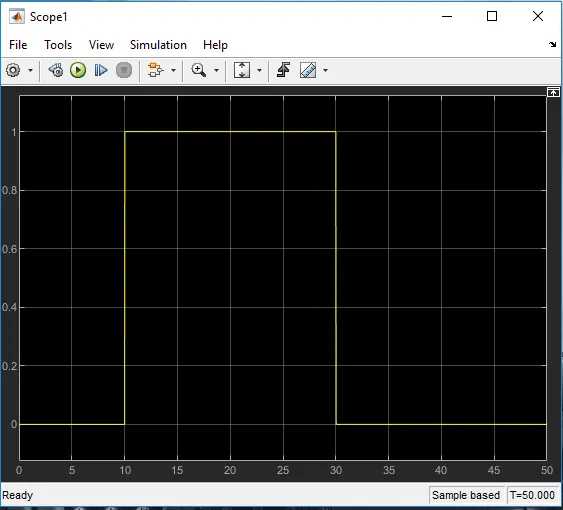
CONCLUSIONS:
1. Thus, both the objectives were achieved successfully.
2. Similar approach can be used for simulating other physical devices using Simulink.