Week 8 - Challenge 4 - Coin Holder Design
COIN HOLDER
Class A surface
Class A surface is given as model.
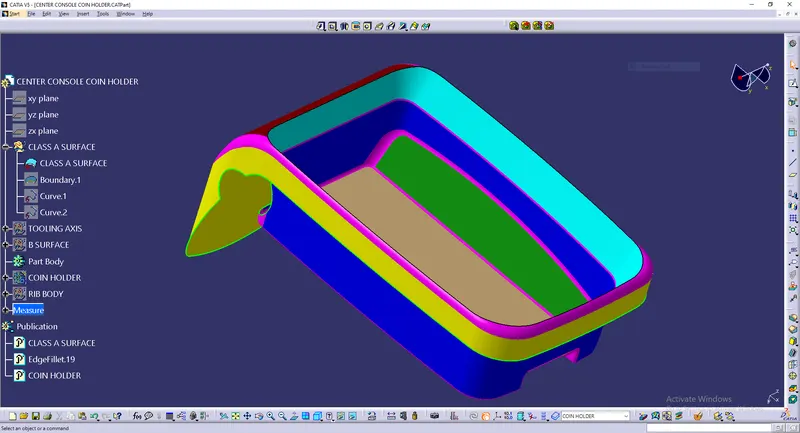
The boundary of the Class A surface is extracted now using extract command.
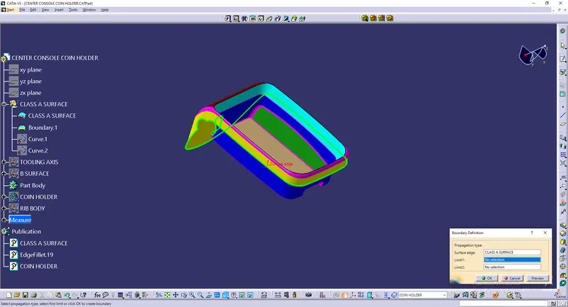
The boundary is extracted into two different curves.
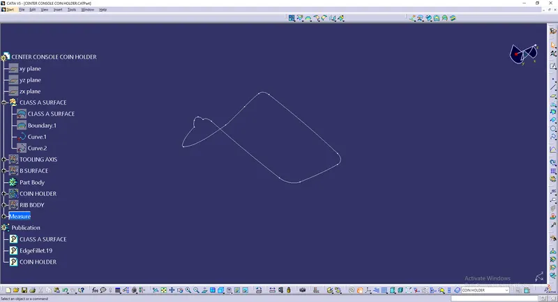
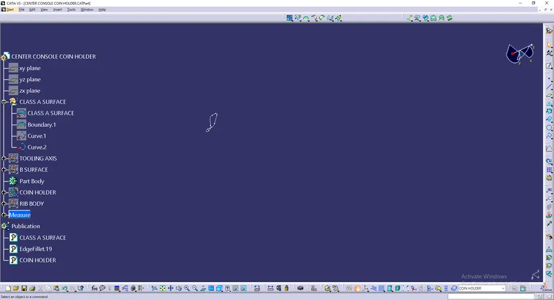
Tooling Axis
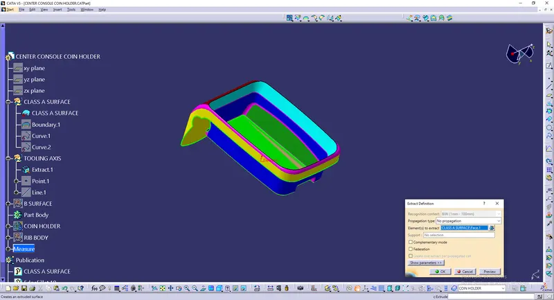
A point should be created on the base surface of the Coin holder. So the surface is extracted using extract command.
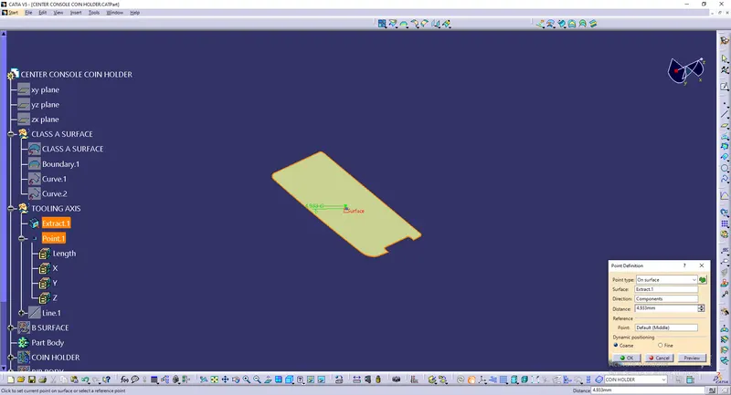
A point is created on the extracted surface.
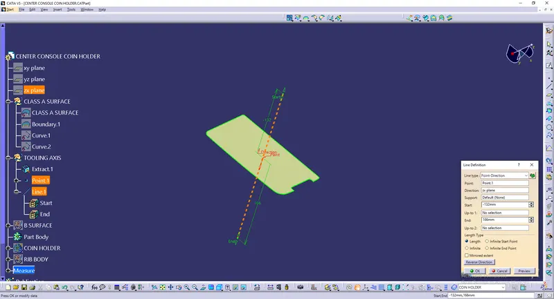
A line is created on the point and directed towards zx plane.
Class B surface
Side walls
Side walls are extracted from the Class A surface using Extract command.
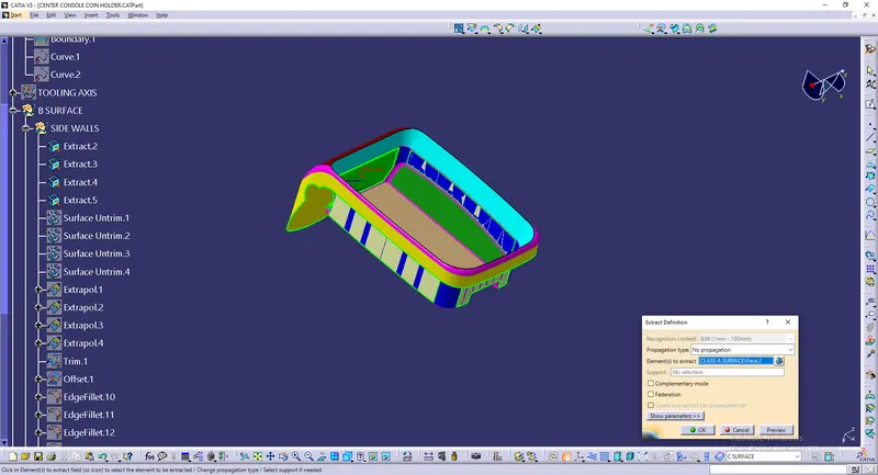
Extracted side walls looks like
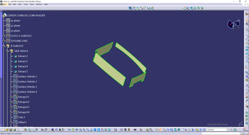
These extracted surfaces are untrimmed using surface untrim
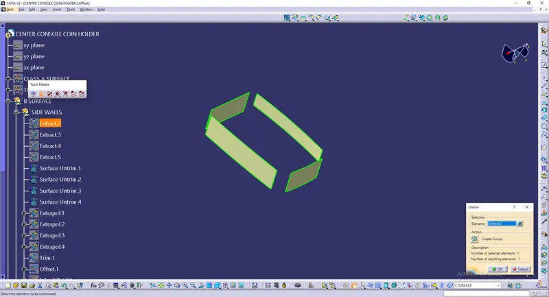
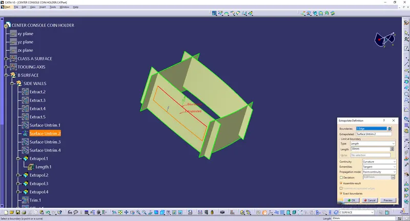
These untrimmed surfaces are extrapolated to certain distance to get intersected with each other.
These extrapolated side wallas are trimmed together using Trim command.
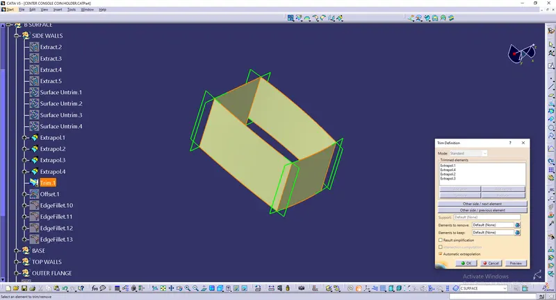
This trimed surface is offset from 2.5mm

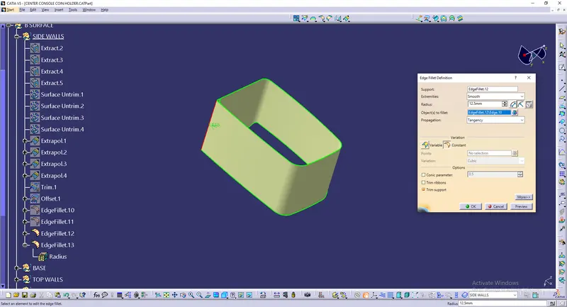
This offsetted side walls surfaces are filleted on the edges as per the Class A surface.
Base
The Base surface is extracted from the Class A surface using extract command.
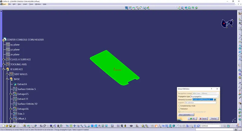
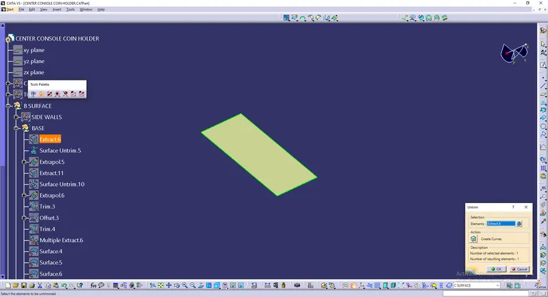
This extracted surface is untrimmed using Surface untrim.
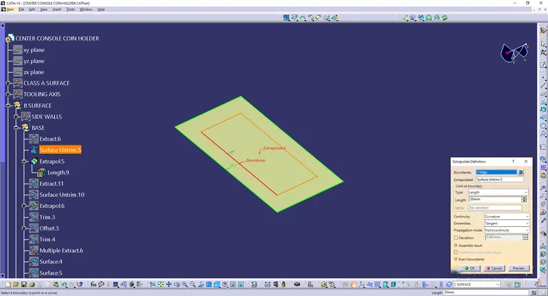
Untrimed surfaces is extrapolated to certain distance using Extrapolate command.
The inclined surface in the Class A surface is also taken into base and extracted using extract command.
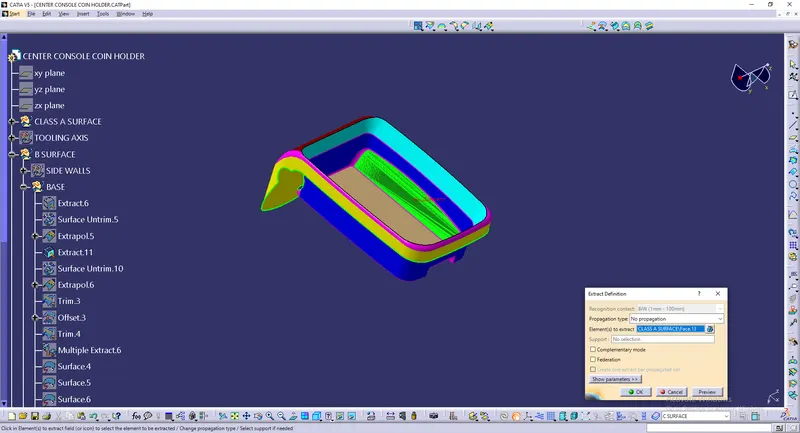
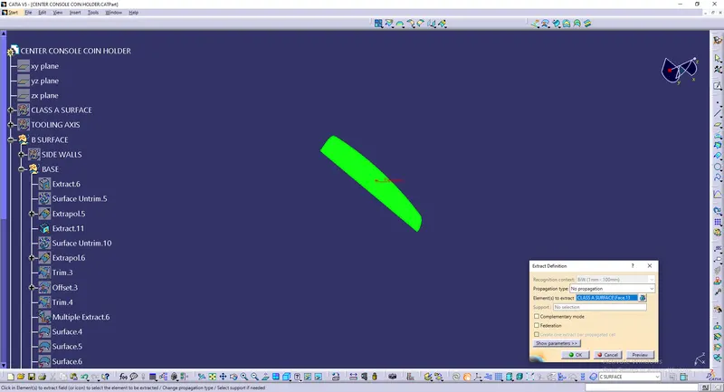
This extracted surface is untrimmed using Surface untrim.
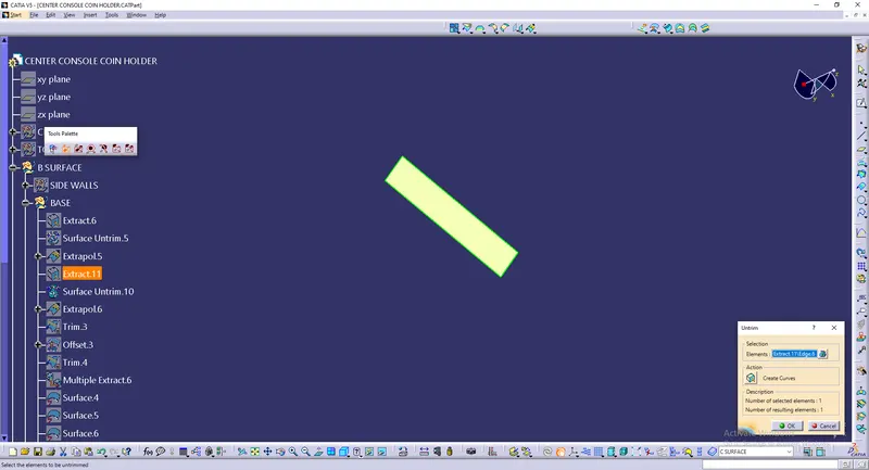
Untrimed surfaces is extrapolated to certain distance using Extrapolate command.
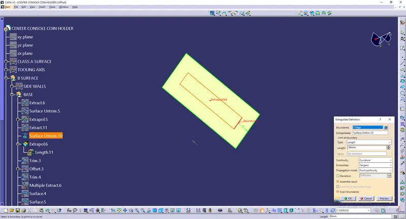
Both the extrapolated base and the inclined surface gets trimmed together using trim command.
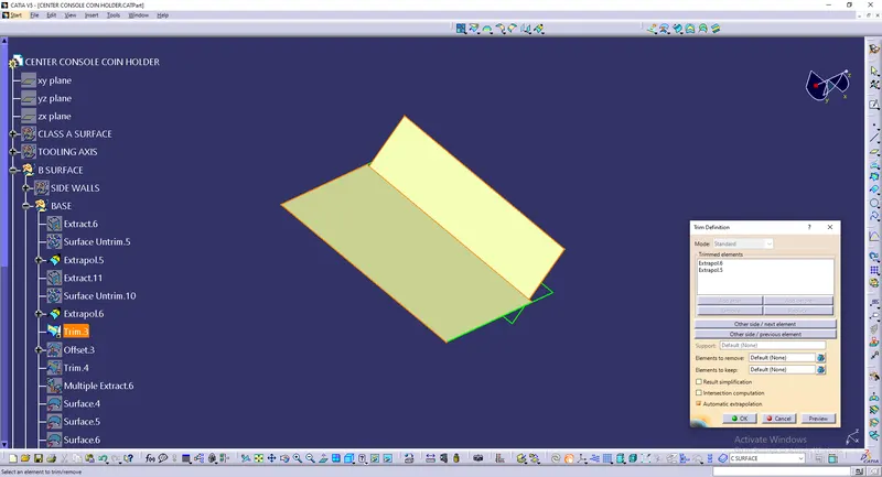
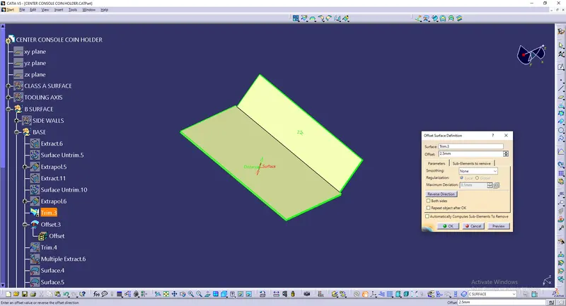
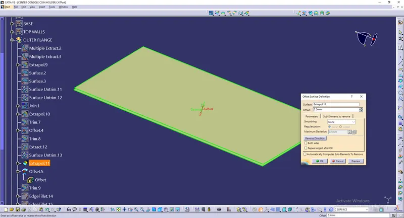
It is offsetted for the 2.5mm thickness value.
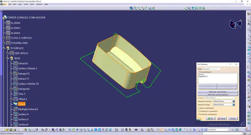
Side walls and the base surface gets trimmed together to get joined.
Another small inclined surfaces is exttracted from the Class A surface using Multiple extract command.
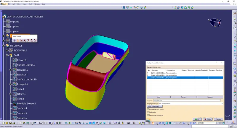
The extracted surfaces looks like
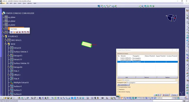
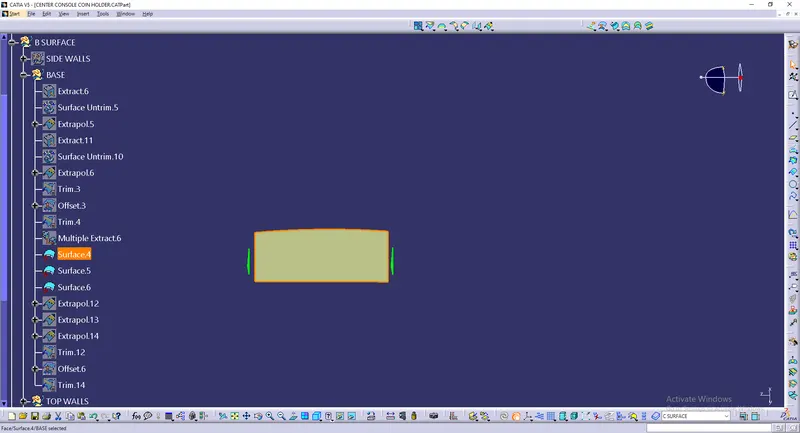
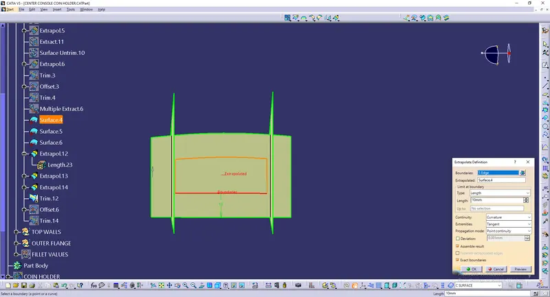
These surfaces are extrapolated to certain distance using extrapolate command.
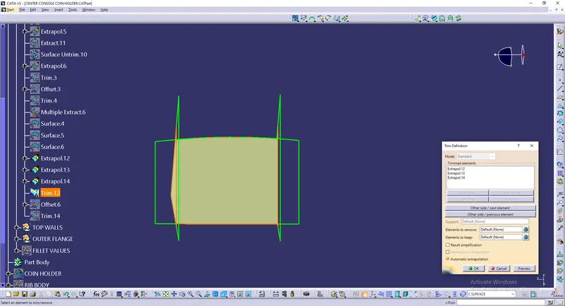
Using trim command these faces are trimmed together
This surface is also offsetted for 2.5mm thickness value but in the negative side.
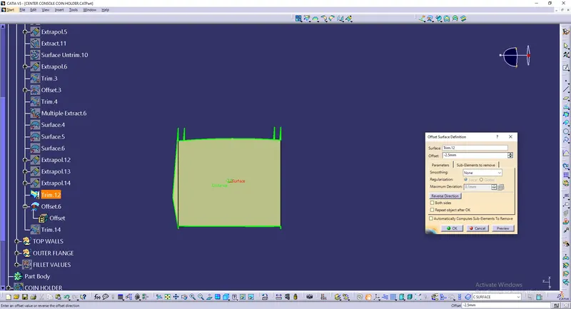
This offsetted surface is trimmed with the base surface.
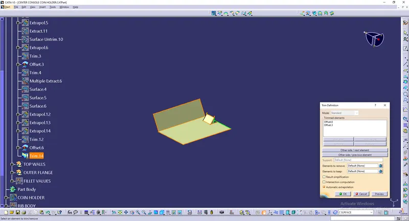
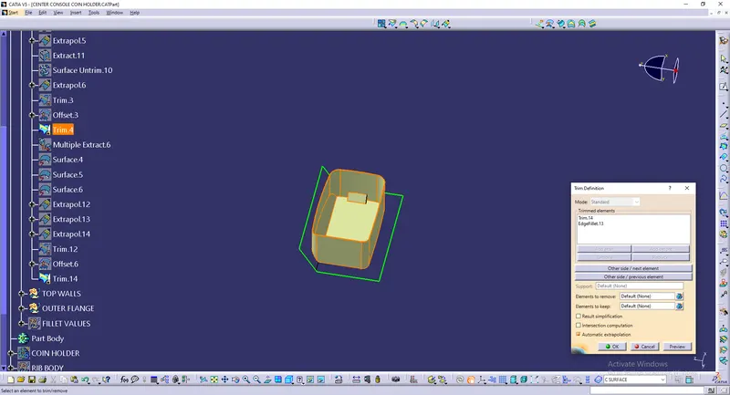
Top walls
Top walls are extracted from the Class A surface using Multiple Extract command.
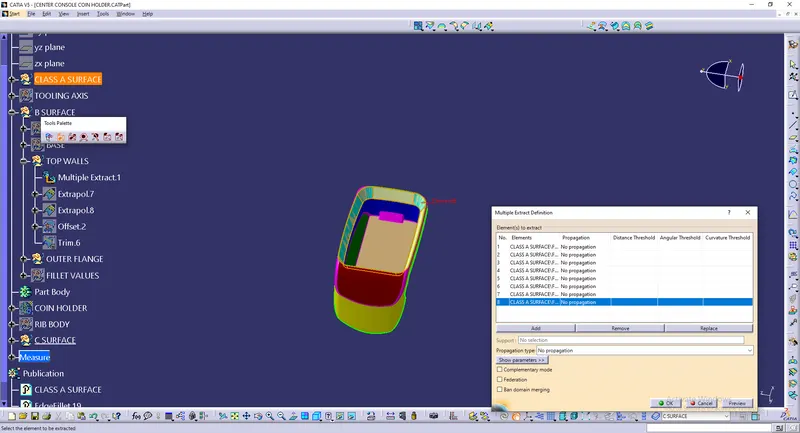
The extracted surface looks like
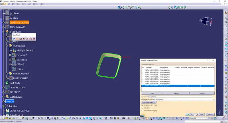
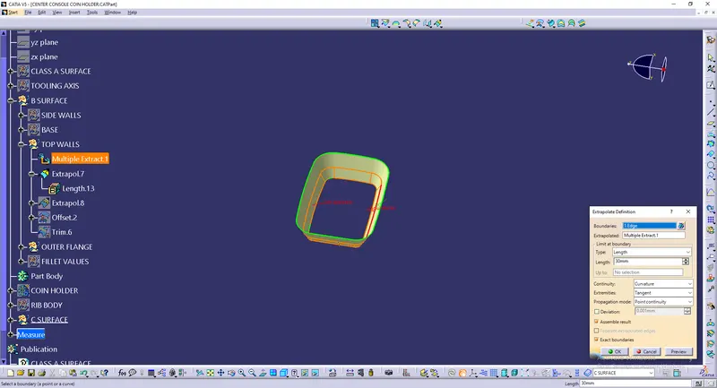
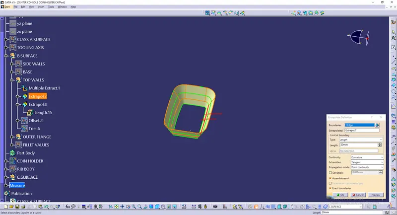
Its then extrapolated to certain distance on both the sides.
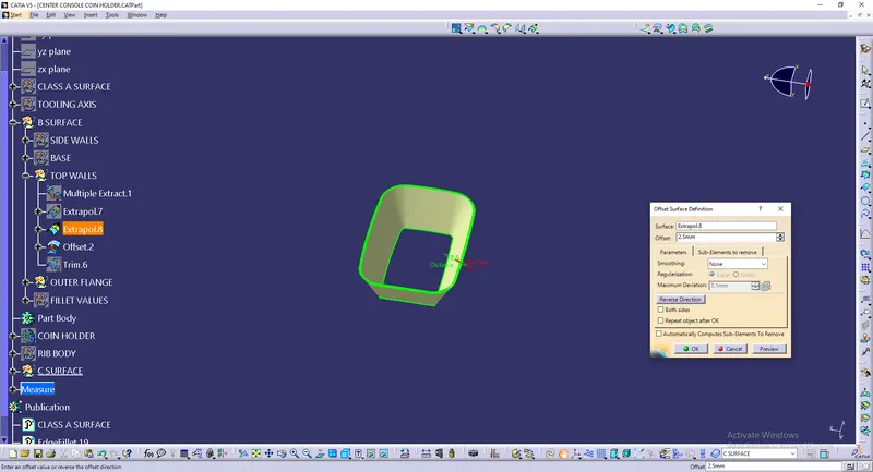
Then offsetted to 2.5mm thickness value
It gets trimmed with the already trimmed surfaces such as Side walls and the Base surfaces
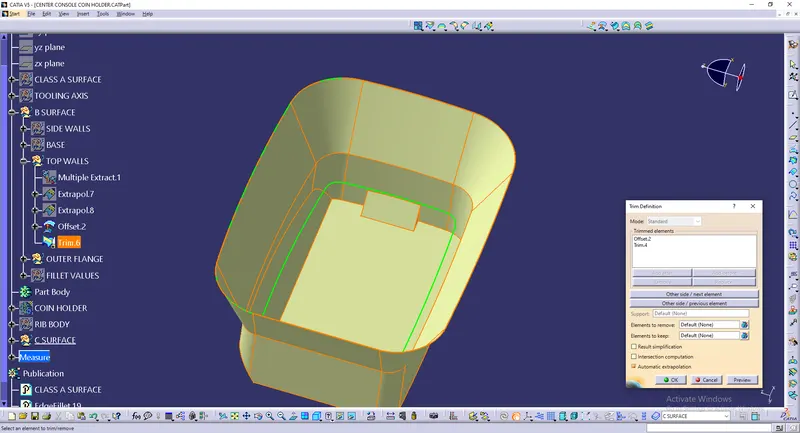
Outer flange
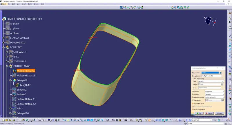
The Outer flange is extracted from the Class A surface using Multiple extract
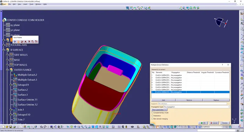
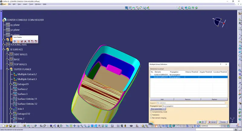
The extracted surfaces looks like
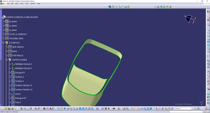
The extracted surface is extrapolated to certain distance.
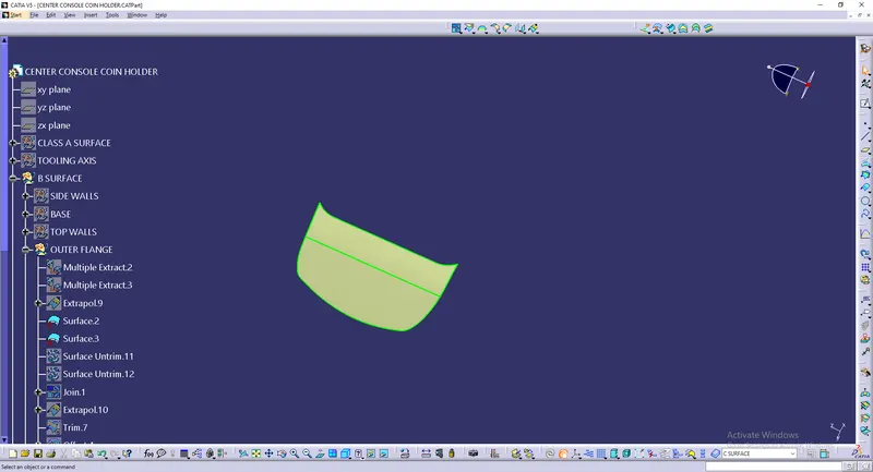
Surface untrim
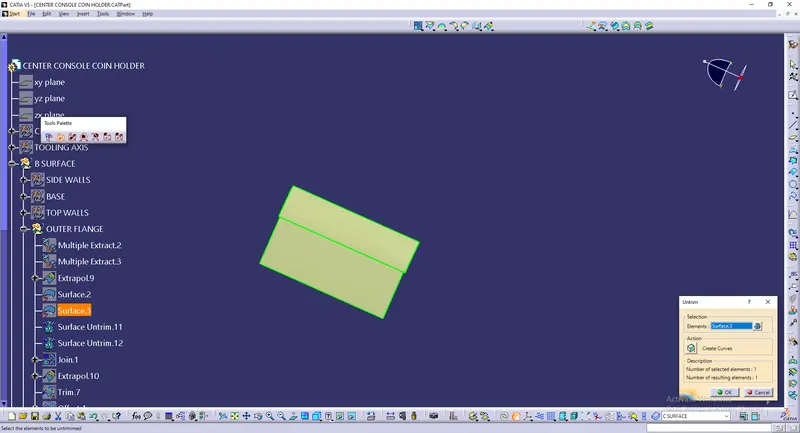
The both untrimmed surfaces are joined together using Join command.
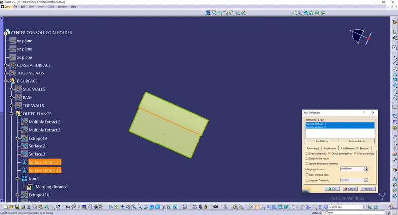
The joined surface is then extrapolated to certain distance.
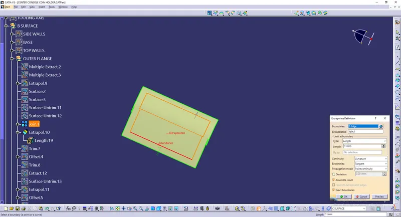
Its gets trimmed with the Outer flange surface using trim command.
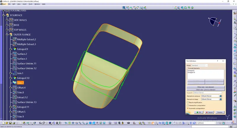
Offset for 2.5mm thickness
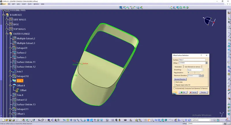
And this offseted surface gets trimmed with the previous surfaces.
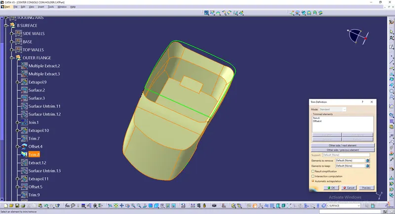
To avoid this raise in the edges,
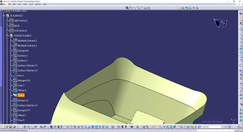
Its extracted, untrimmed, extrapolated, offset to the thickness and trimmed with the main surfaces.
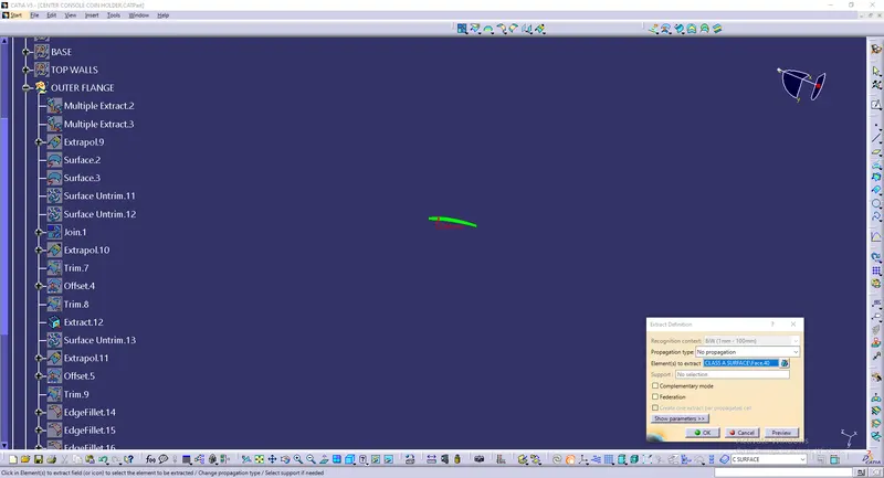
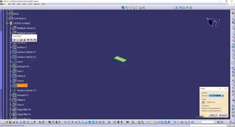
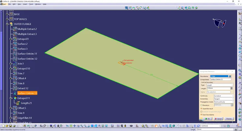
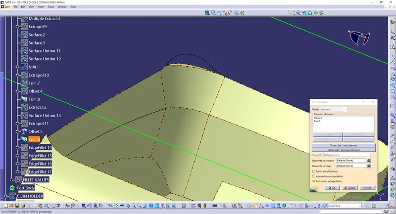
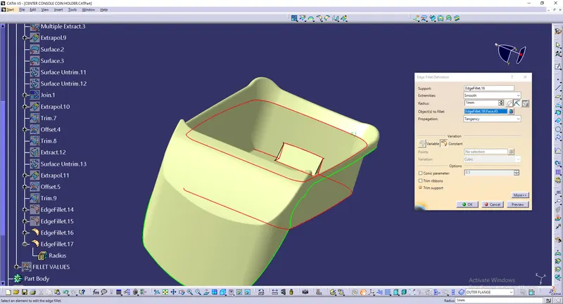
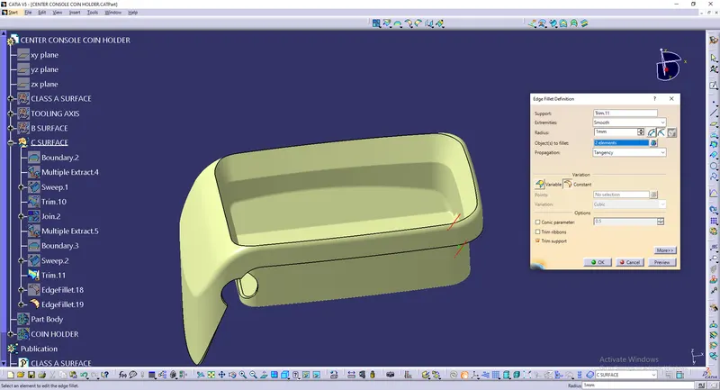
Now the edges are filleted using Edge fillet command.
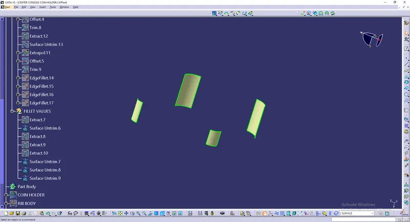
The Filleted surfaces are extracted and measured for filleting the Class B surface.
Class C surface
The boundary from the Class A surface is extracted
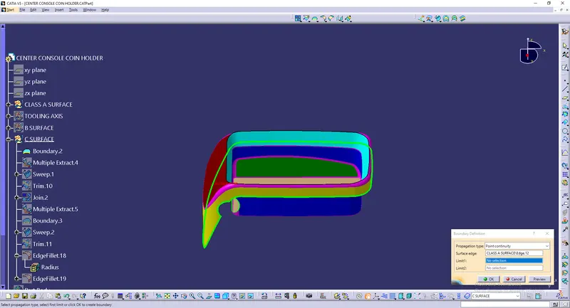
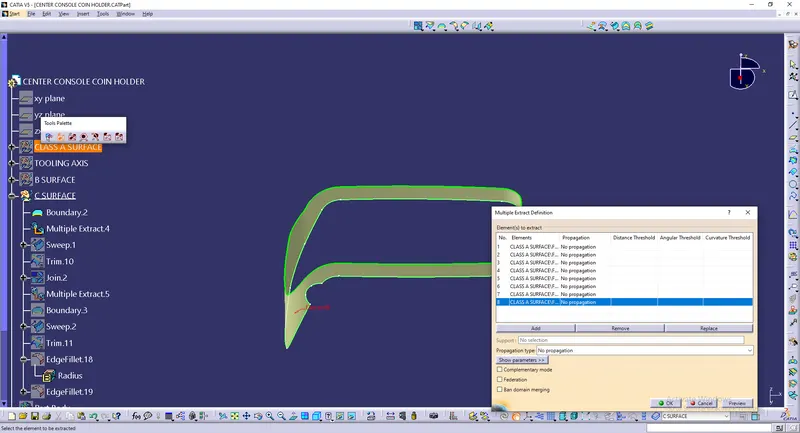
The Outer flnage is extracted from the Class A surface using Multiple extract.
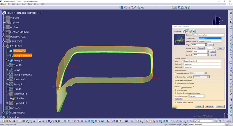
Sweep
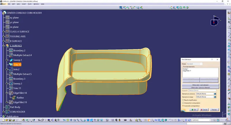
Its get trimmed with the Class B surface using trim command.
Class B surface and Class C surface is joined. Now these are joined with the Class A surface.
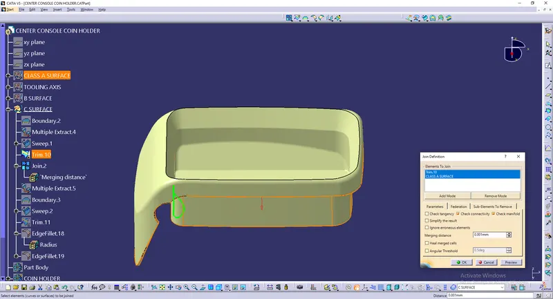
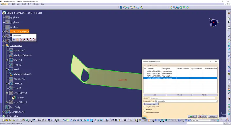
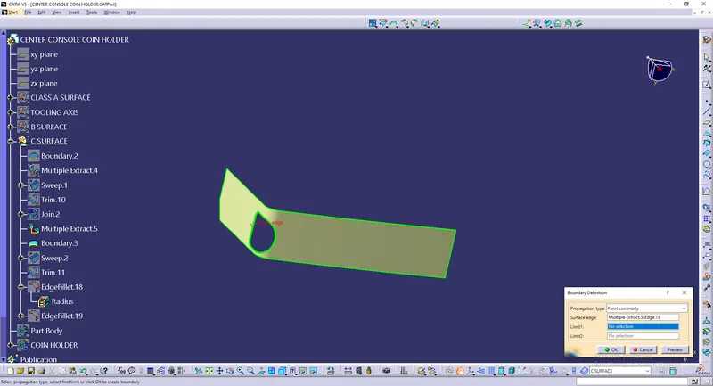
A hole is missing, so to get the hole in the Class A surface here. Its boundary is extracted and sweeped and trim is done.
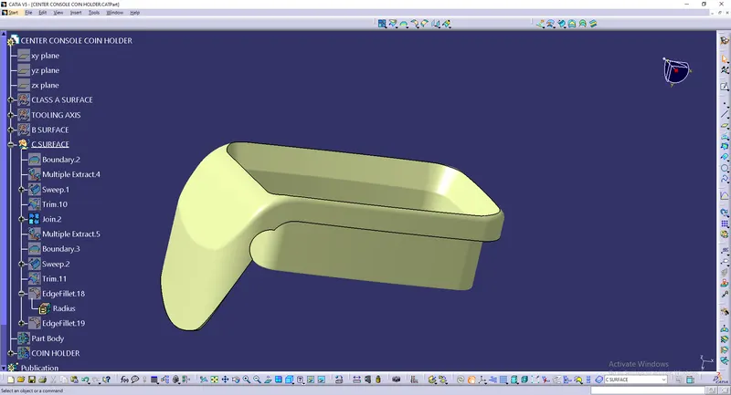
Multiple extract
Boundary extraction
Sweep
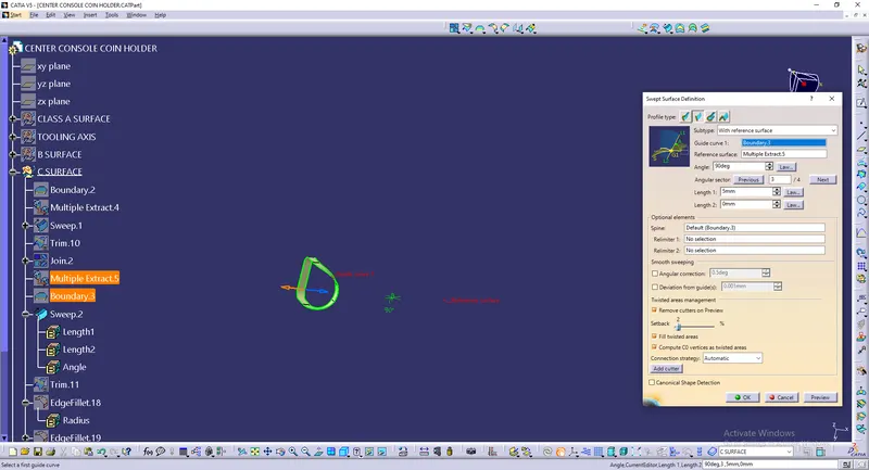
Now this sweep gets trimmed with the previous surfaces.
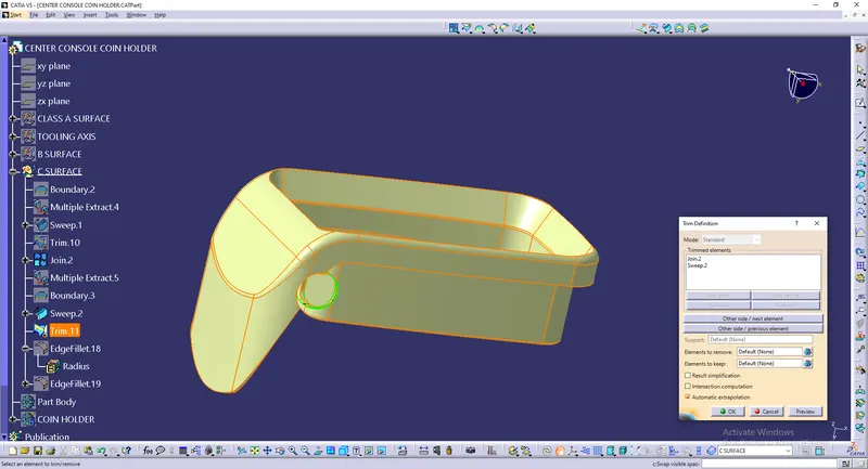
Fillet
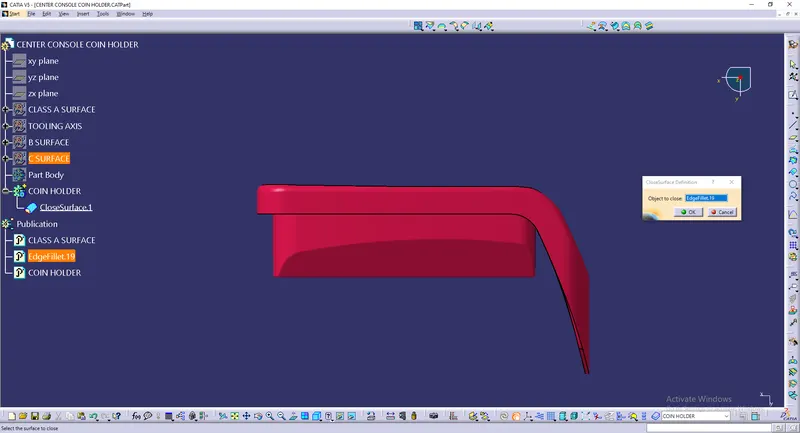
Solid
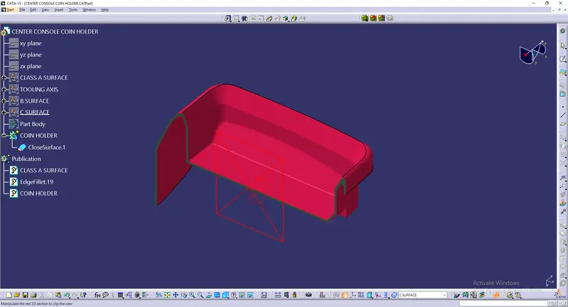
The above surface is converted to solid suing closed surface option.
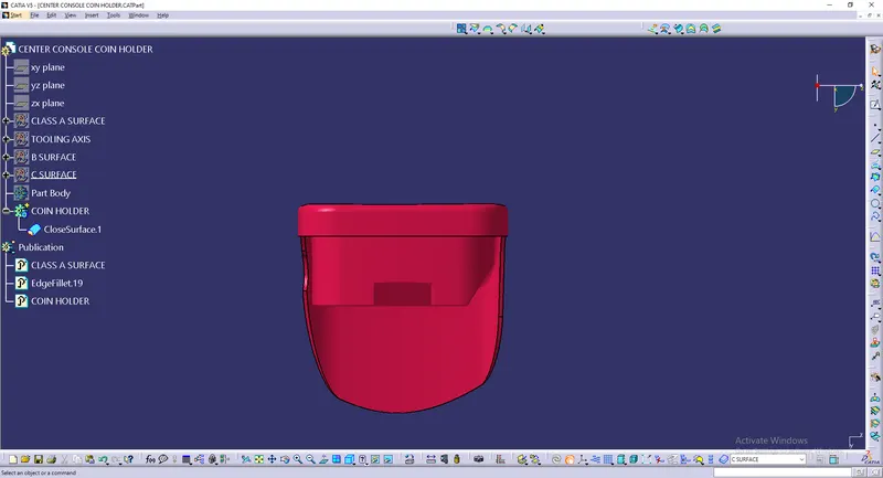
Front view
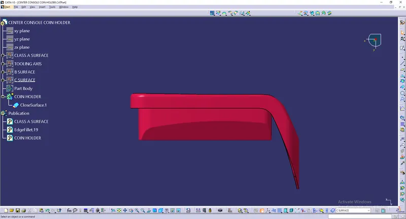
Side view
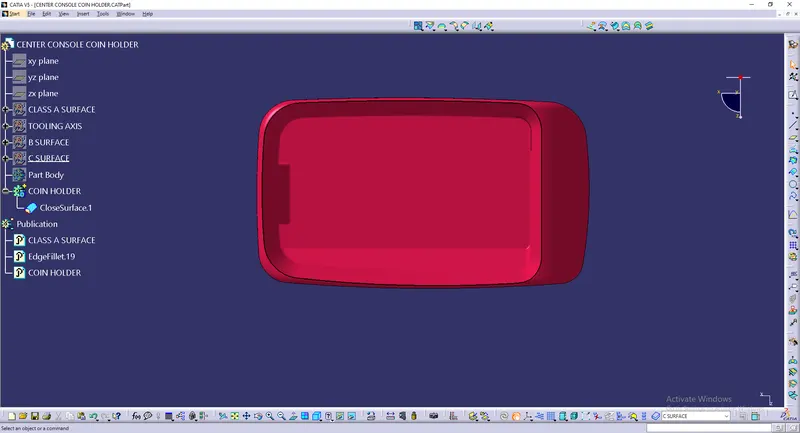
Top view
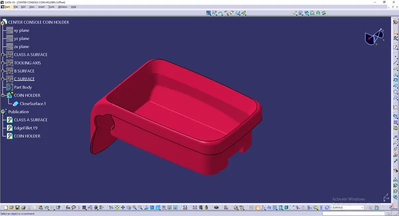
Isometric view
Dynamic Sectioning
Draft analysis
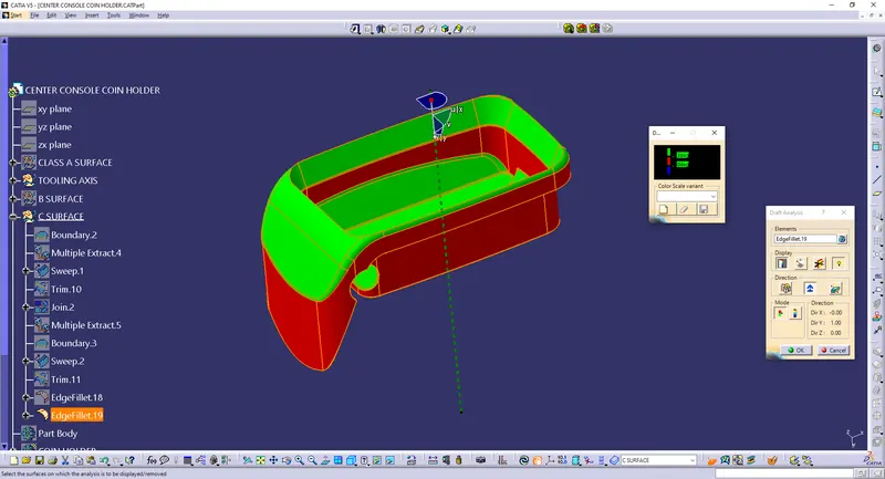
Here as the Class A surface is very complicated, Some area inside the Class A surface will be passing the criteria of 3deg.