Week 8 - Challenge 4 - Coin Holder Design
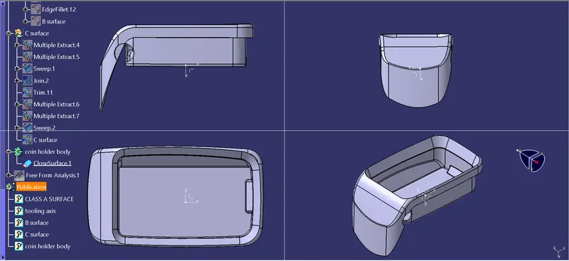
The 3D model for the given coin holder is created with the given class A surface then followed by creating class B and C surface and done draft analysis for the created 3D model and the given class A surface:
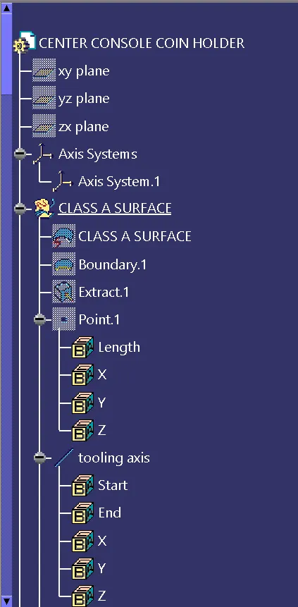
Creating tooling axis:
The given class A surface is downloaded and opened. It is checked to have closed surface. Then the boundary line is created and the base is extracted to draw the tooling axis.
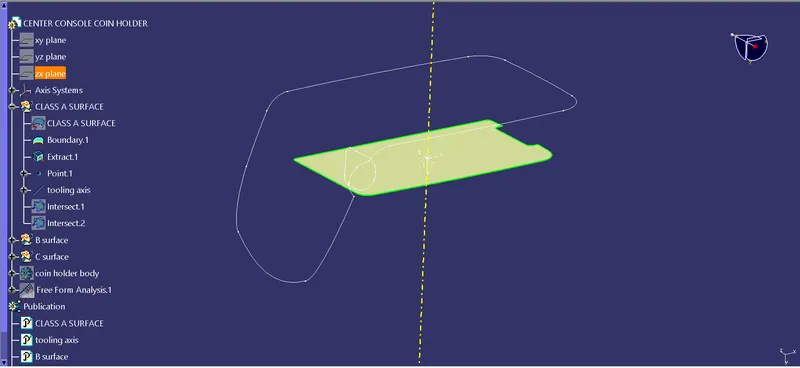
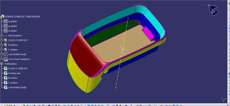
Draft analysis for the class A surface:
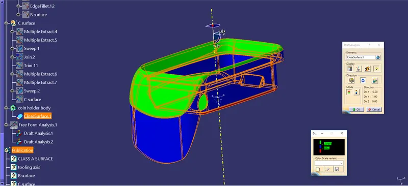
For draft analysis, the compass is placed on the tooling axis in a way where the tooling axis is alinged parallel to the w axis in the compass. And locked the draft direction. As the compass is inverse the draft may give values in oppsite for that the inverse command is picked to inverse the draft value.
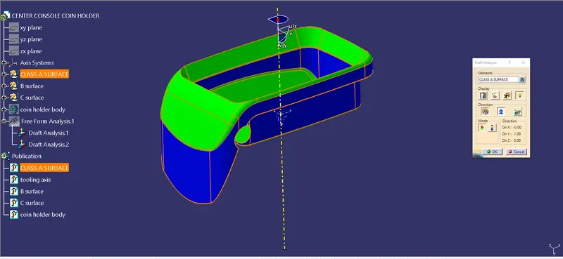
Creating class B surface:
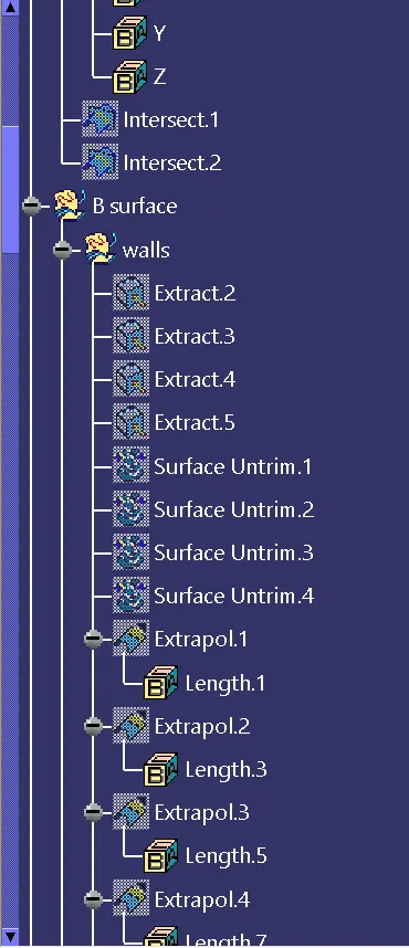
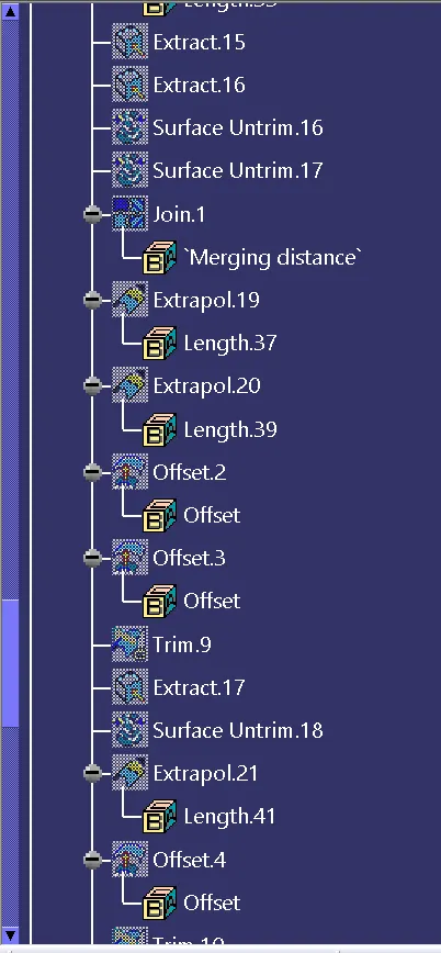
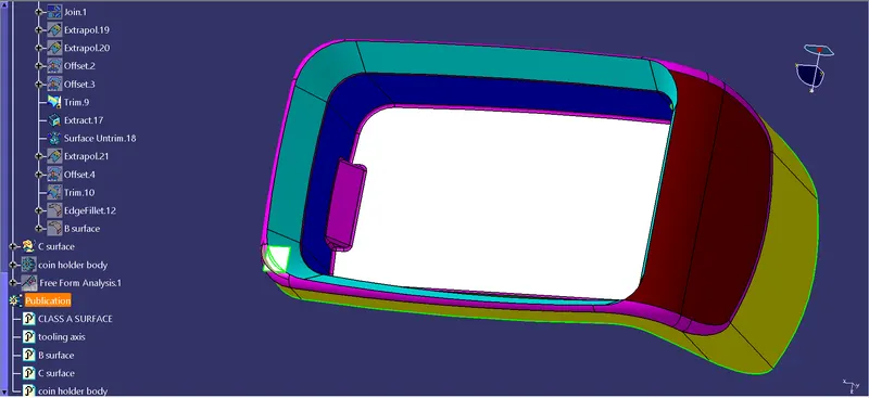
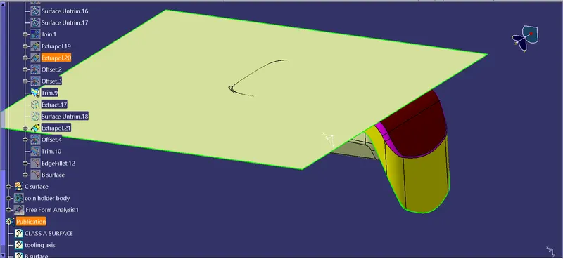
To create the B surface first the side walls are been extracted, untrimed and extrapolated.
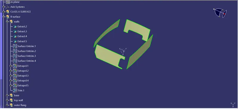
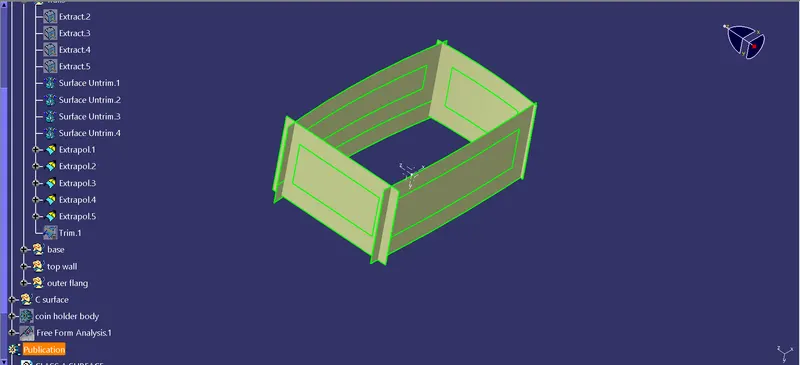
Then these are trimed and checked with the class A surface to ensure that it is correct.
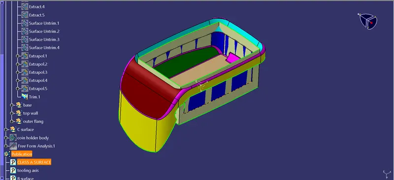
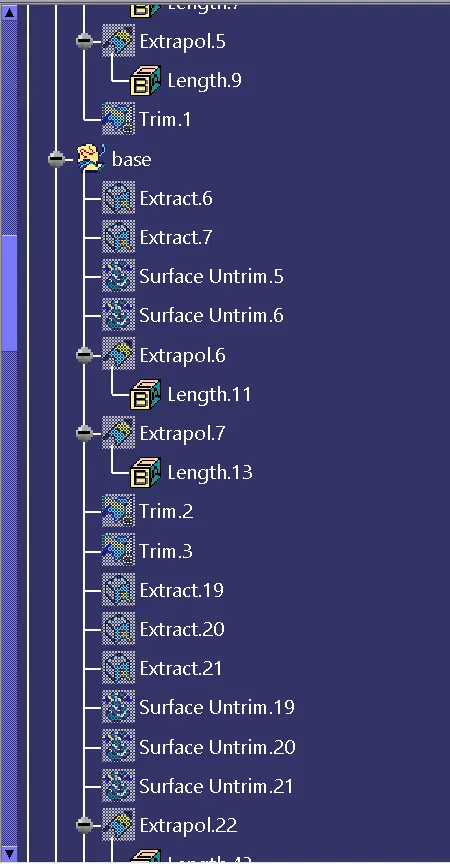
Then the base is extracted and trimed with each other after untrimming and extrapolating it.
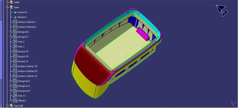
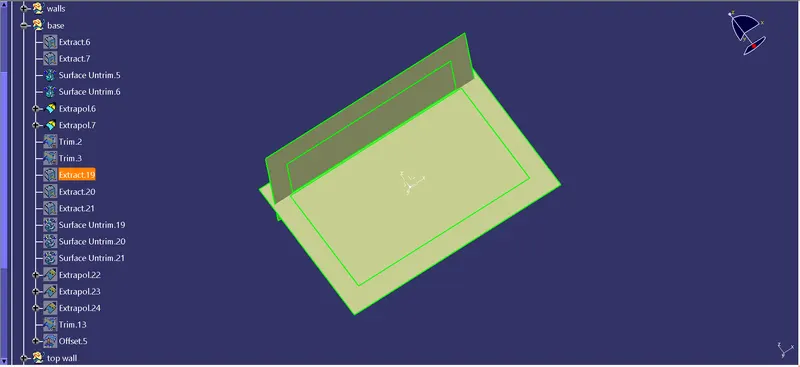
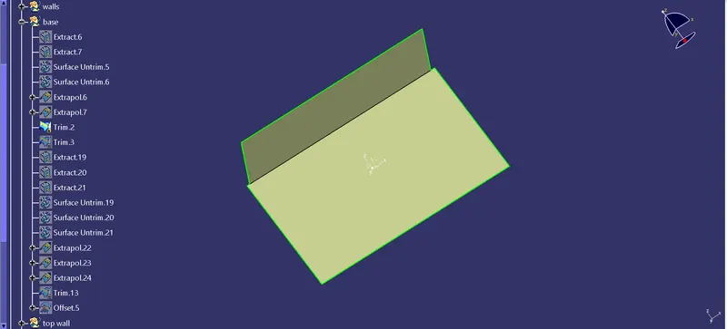
After trimming the base with each other, it is then trimed to the side walls to form a box like.
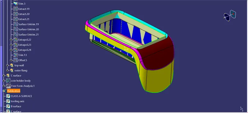
Then to create the bump in the box like. They are extracted and trimed with eachother after extrapolating. As they are already in a square/rectangle in shape untrim will be no other difference.

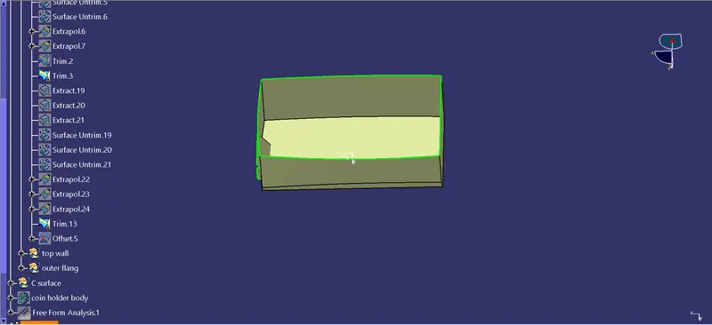
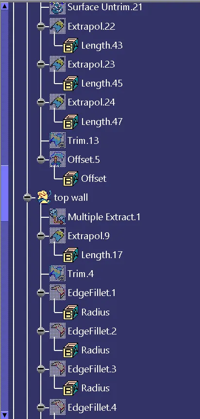
To created the top wall, The top is extracted using multiple extract as they are a single part. Then it si trimed with the box like after extrapolating it.
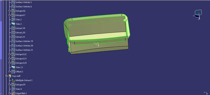
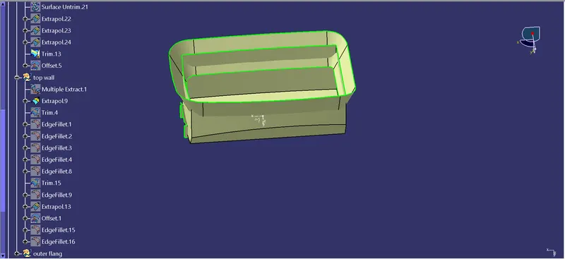
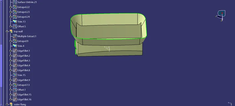
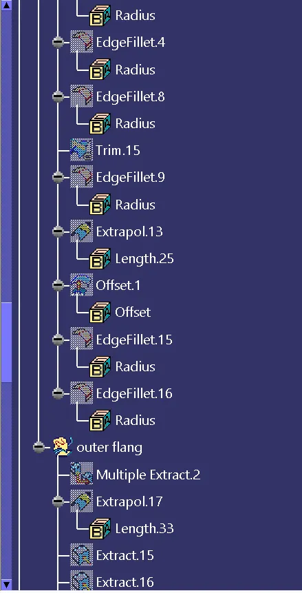
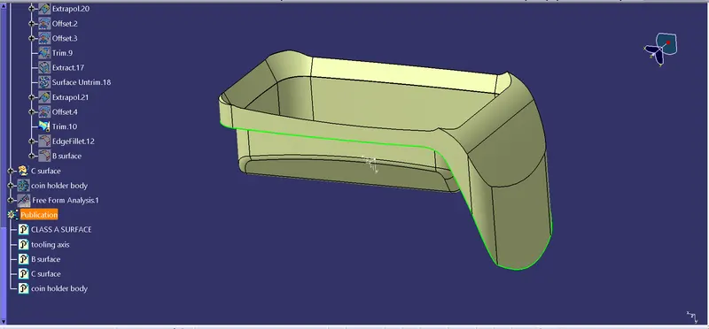
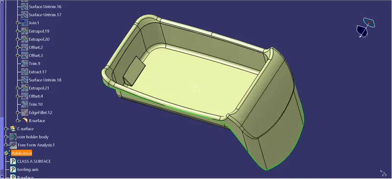
The edge fillet is given to the edges and brought it to the shape. As they have different fillet values in each side. They are given individually. The bump and the side base is also filleted.
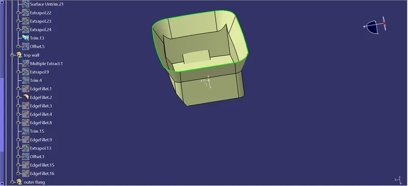
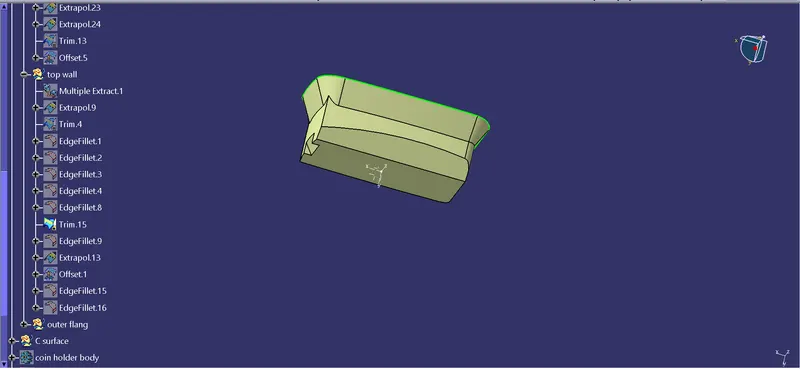
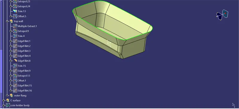
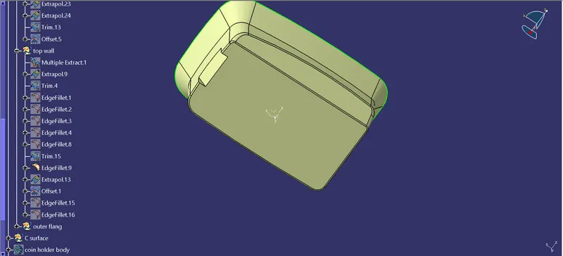
This is then offsetted to 2.5 mm as peer asked.
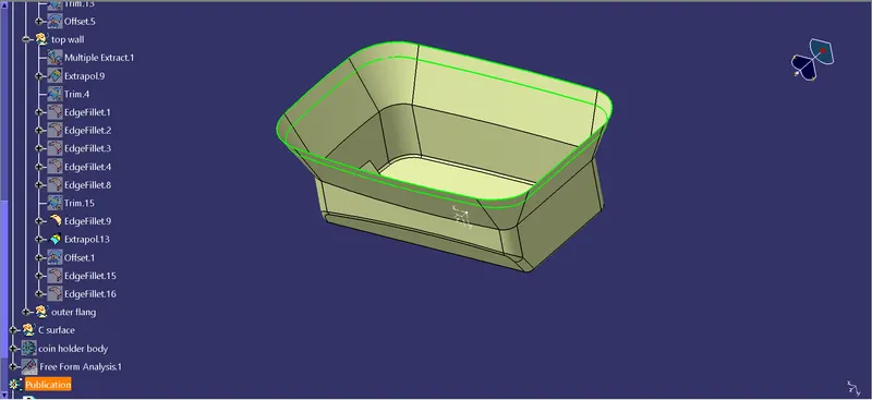
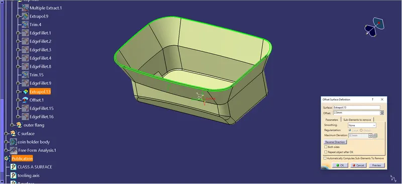
Class A surface is showed and checked.
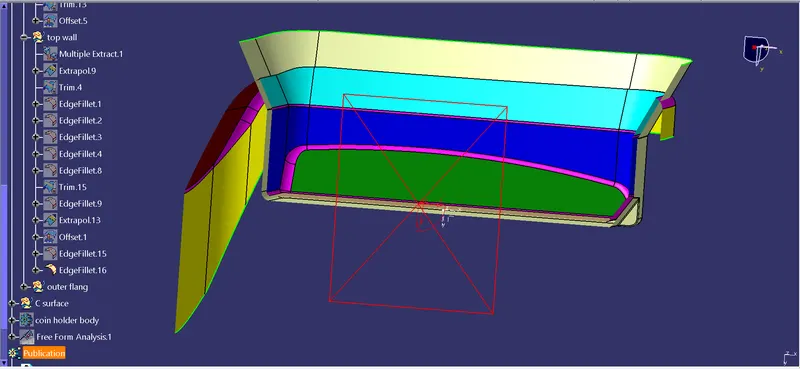
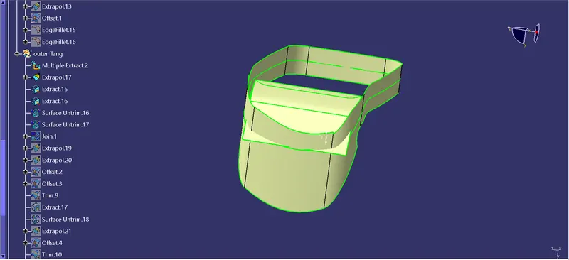
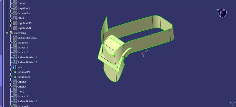
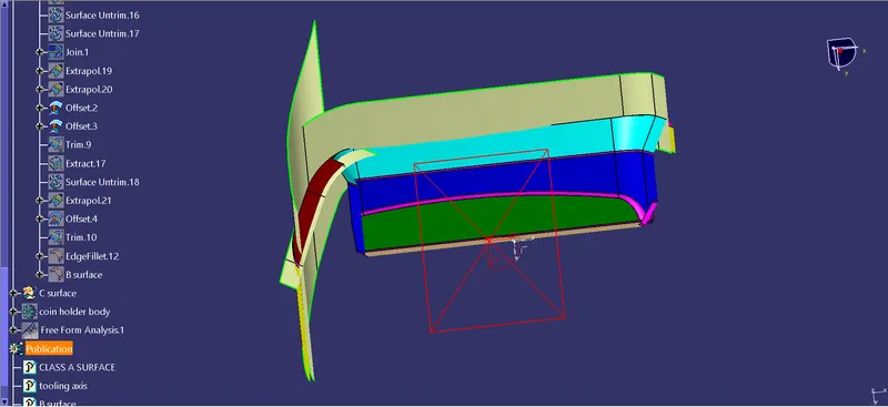
After extracting and trimming every surfaces it is filleted to form the requiired shape.
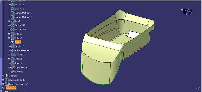
Creating class C surface:
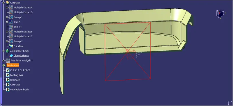
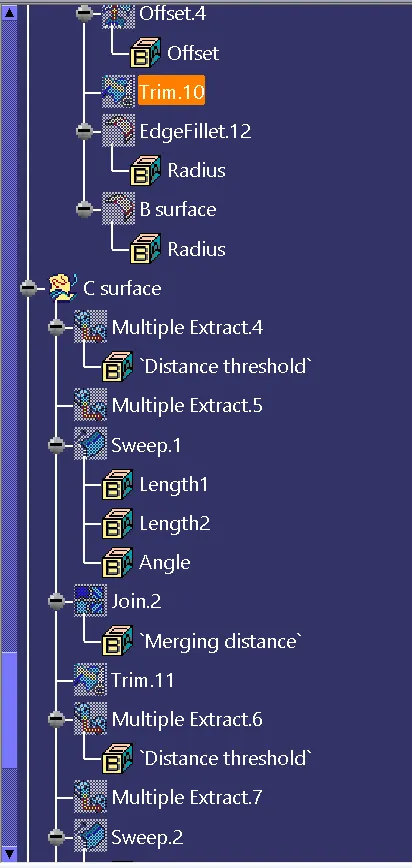
To create the C surface the boundary line of the A surface and the outeer surface is extracted which is close with the boundary surface.
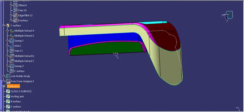
Sweep command is used to create the closing surface.
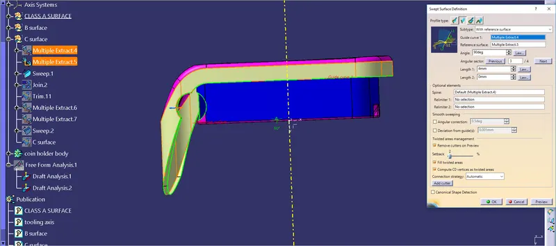
Then the A surface and the sweep surface is joined.
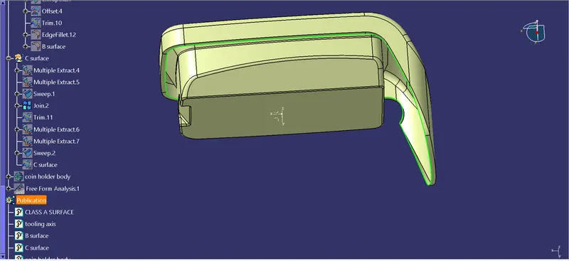
Then the B surface is trimed with this and formed a closed surface body.
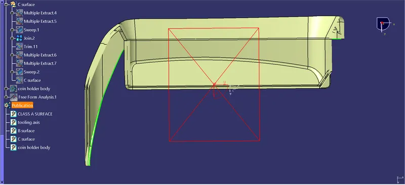
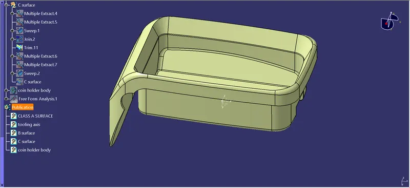
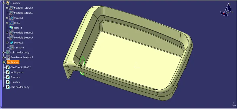
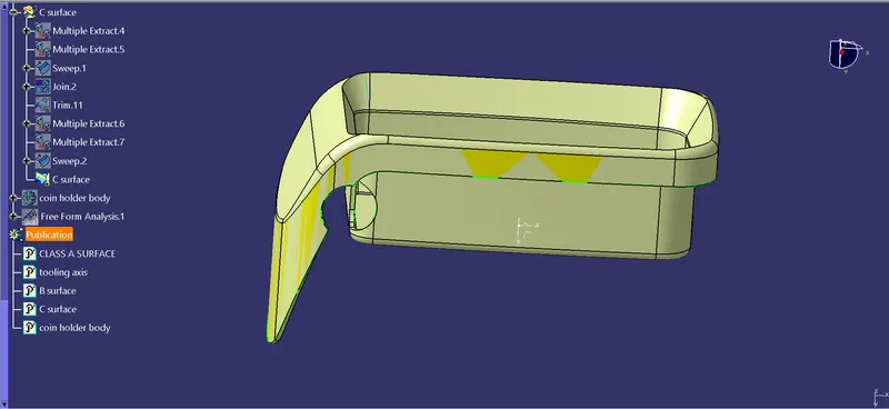
Creating the side hole:
The boundary line of the hole from the class A surface is taken.
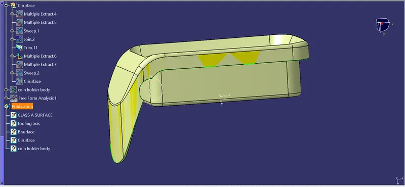
Then the adjacent surface of the hole from the class A surface is taken.
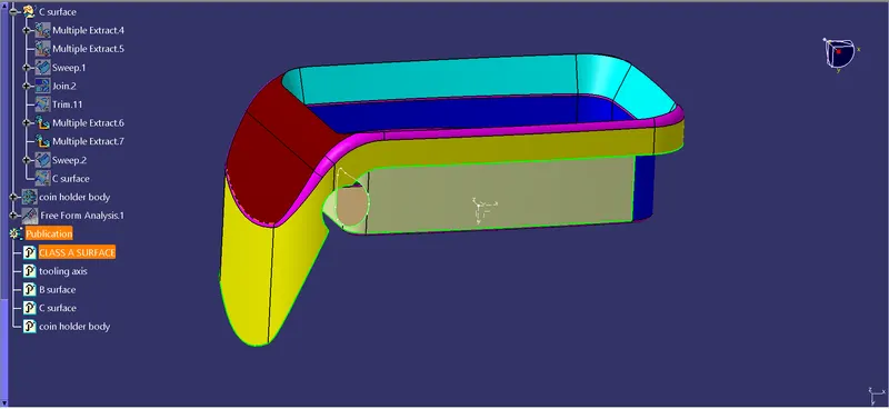
The hole is sweept and trimmed from the C surface.
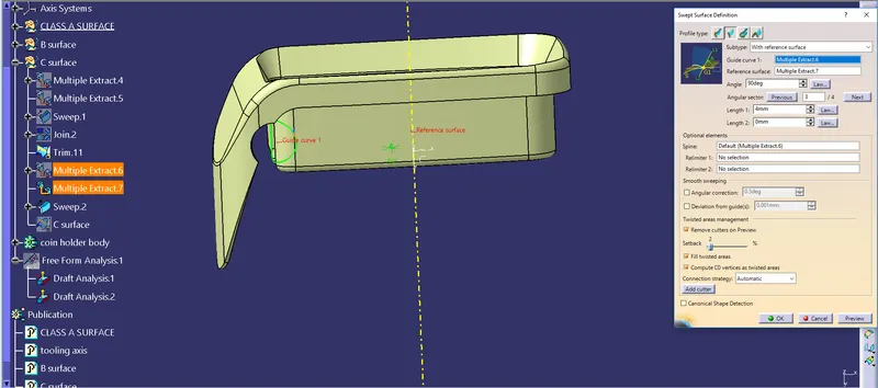
Filling the surface with solid:
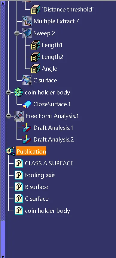
After making the close surface, it is then filled with solid using close surface command in part modelling. And then draft analysis is done for the solid model.