Week 8 - Challenge 4 - Coin Holder Design
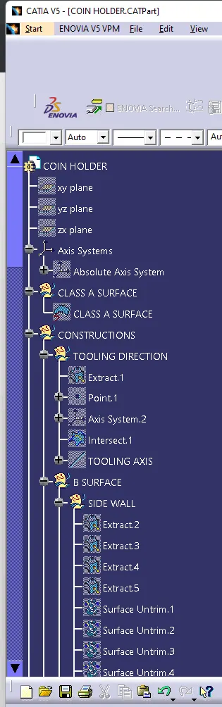
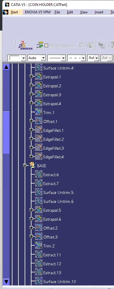
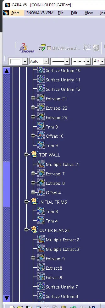
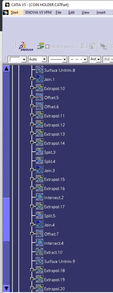
TREE STRUCTURE:
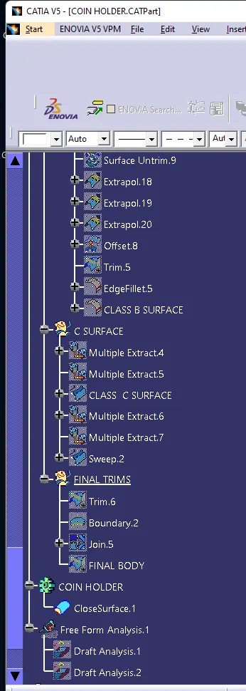
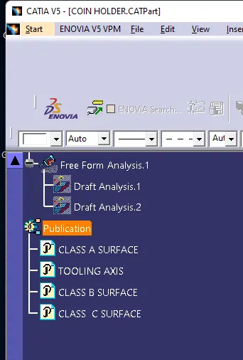
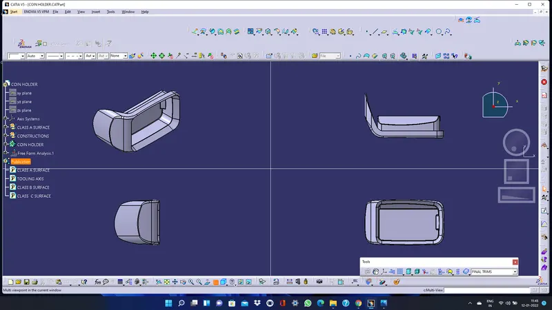
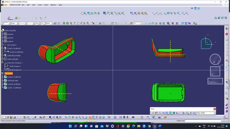
VIEWS:
REPORT:
AIM:
A class-A surface has been provided to me for designing a full solid body out of a surface and validate it.
OBJECTIVE:
The objective of the project is to design the Coin Holder from the Class-A surface to the final solid model and the draft analysis on the model is also performed for the created tooling direction.
In given surface first I need to check any open boundaries that may create errors while designing.
- After checking I need to create a tooling axis for the class-A surface.
- Then I need to create class-B and class-C surface with the help of the class-A surface.
Tooling axis creation:
The tooling axis is important for removing the material when finished.
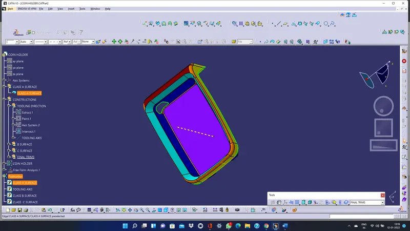
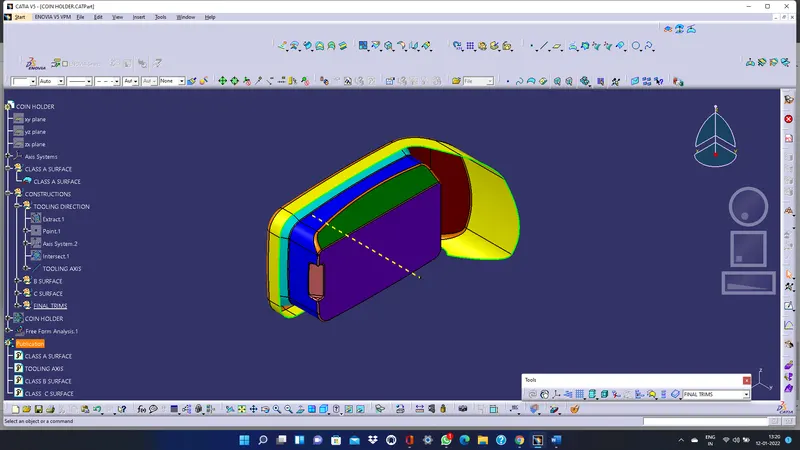
First, I will creating the point on base surface respectively also extract the surface of the component as shown in image.
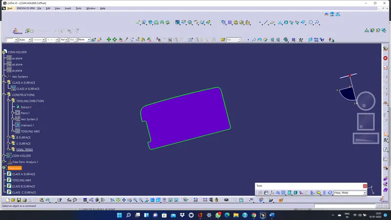
After we create a point on the extract surface,then insert a axis system.Let we check the instersection between yz plane and class a surface.
Creating a line like by using normal to surface, here surface is extract body.Finally tooling axis is created.
DRAFT ANALYSIS:
INTRODUCTION:
- The Draft Analysis command enables you to detect if the part you drafted will be easily removed. This type of analysis is performed based on colour ranges identifying zones on the analysed element where the deviation from the draft direction at any point, corresponds to specified values.
Tooling direction is the main consideration for plastic part and mould parts because it defines the movement of the mould part and the possibility of the plastic part coming out from the mould part (Core and Cavity).
- What is Draft?
Draft is providing angles or tapers on product features such as walls, ribs and bosses that lie parallel to the direction of release from the mould eases part ejection.
Draft allows for the parts to release from the mould.
- Draft is required on all parts in the direction of mould movement in order to allow parts to release or eject form mould properly.
Draft is the angle in which the parts is tapered to allow it to release. As the part cools, it tends to want to shrink to the core side of the mould.
Adding draft helps the part to release. Most parts or applications require minimum of 1/2 to 1 degree, however 3 degrees is widely accepted as the norm.
DRAFT ANALYSIS:
- For plastic parts, the nominal angle value for draft analysis is 3 degree burevena 0.5-degree angle can be created for sub assemblies like ribs and slots. (For Sheet Metal 7 degree angle is the nominal value)
- Insert - Analysis-Feature Draft Analysis.
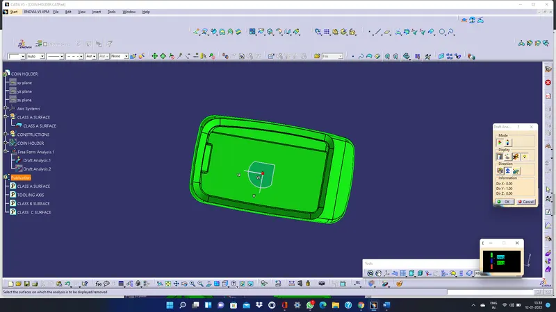
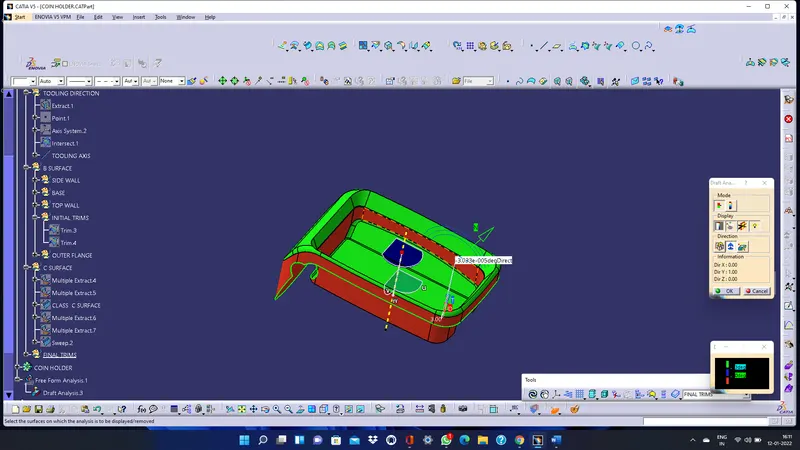
Draft analysis was carried out by pulling the compass to the tooling axis and an inverse draft axis was carried out if required.
After setting the compass over the tooling axis the compass must be locked to a specific direction
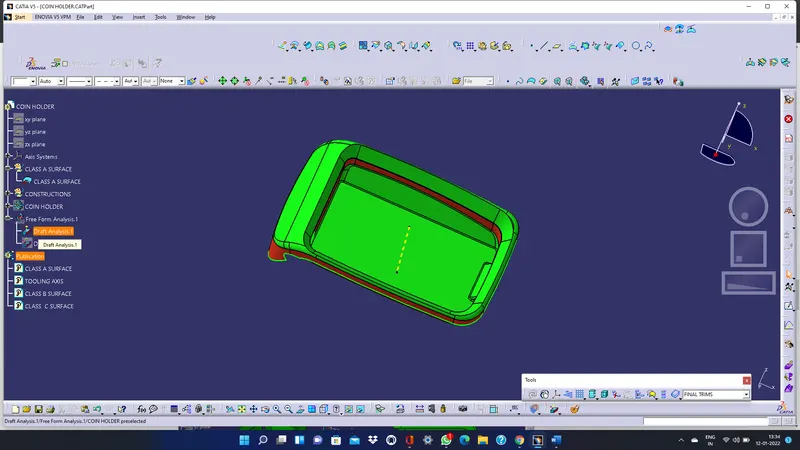
If the surface was in green then the model passes or else further operations need to be carried out.
PROCEDURE:
First the class - A surface is checked before creating the Class-B&C surface and finally the solid body must be analysed: Both can be done by following the below procedures.
By changing the view mode to custom view parameters-Material mode then the feature draft analysis is enabled.
Then the compass was activated and placed with the tooling axis by dragging the red pointer and then locked it.
Then, by selecting the quick analysis mode, the nominal value will be 3 degrees and checked for the component's draft angle.
CLASS B SURFACE & CLASS C SURFACE:
CLASS A: It is the outermost surface of the automobile which gives aesthetic look to the vehicle, it is physically touchable. It is obtained from clay modelling by reverse engineering. This surface is given input to plastic product designer to work
CLASS B:This surface is created by taking offset of 2.5mm from class A surface. It is the surface on which all engineering feature like screw bosses, dog house, ribs & mounting are created.
CLASS C:This is the surface that joins class A & class B together.
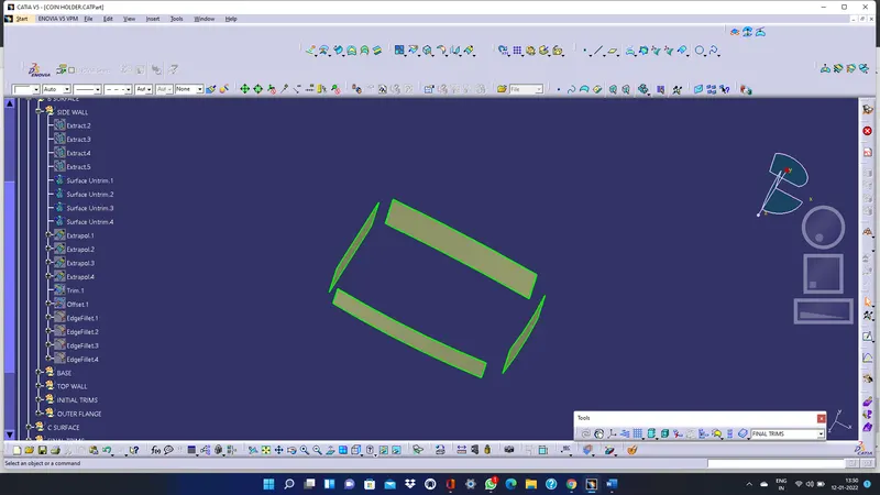
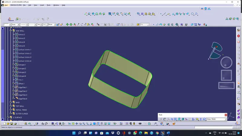
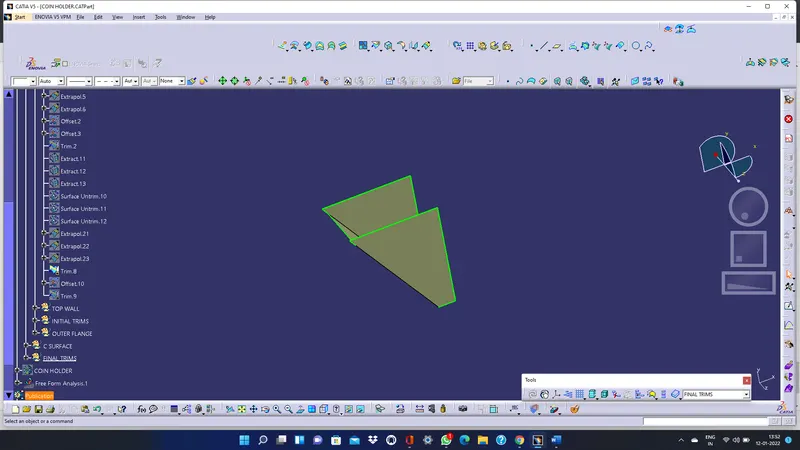
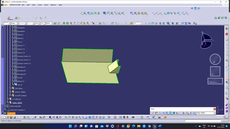
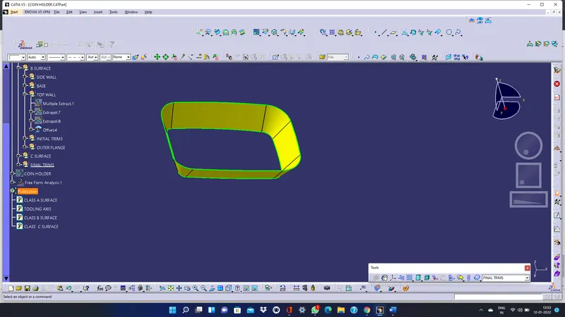
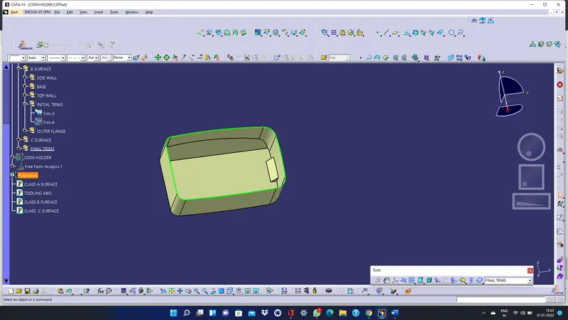
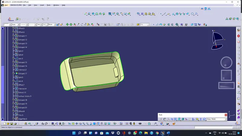
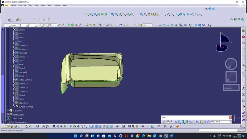
Creating the B-surface by extracting the class-A surface by each surfaces separately it is untrimmed and extrapolated to certain distance using point continuity for uniform extension all over the boundary. After that we trim the surfaces to the desire shape and offset the surface to 2.5mm.Starting from the base part of provided Class-A surface.
SIDE WALLS:
BASE:
TOP WALLS:
INITIAL TRIMS:
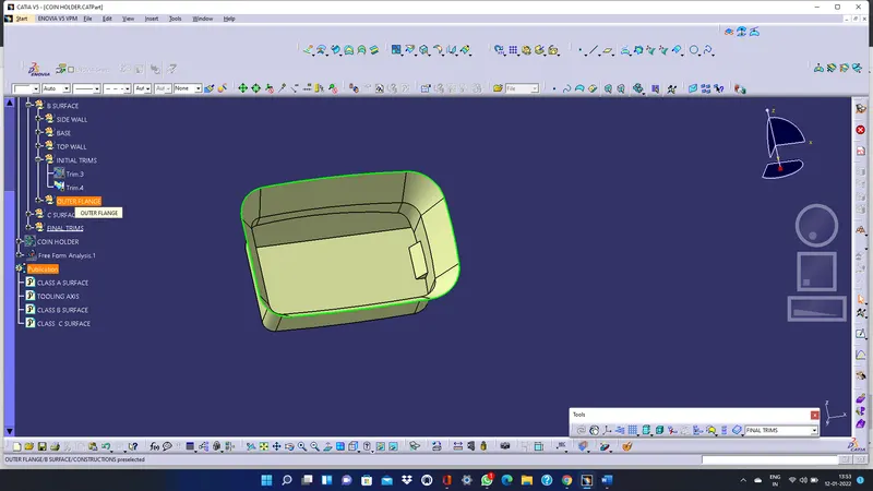
OUTER FLANGE:
C SURFACE:
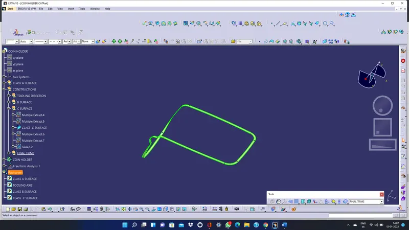
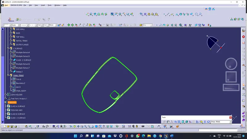
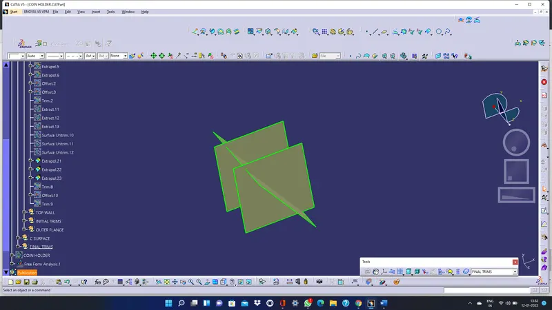
FINAL TRIMS:
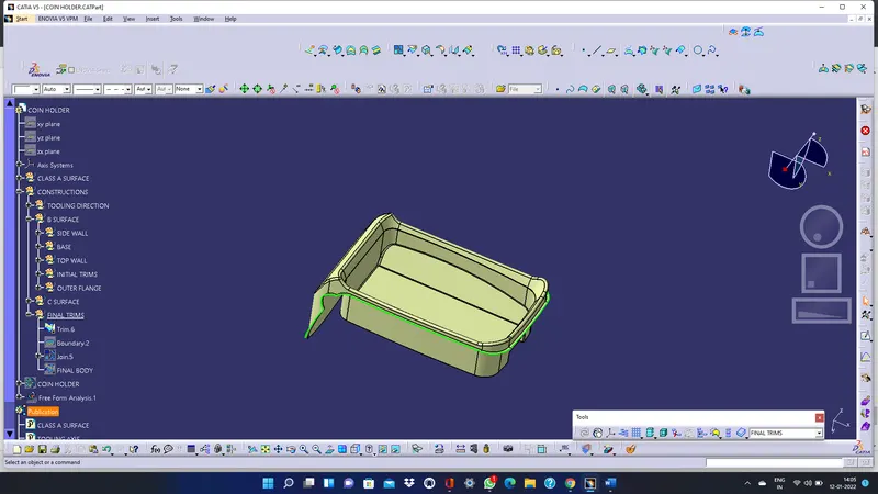
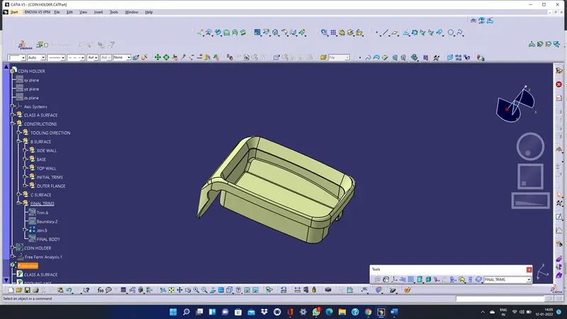
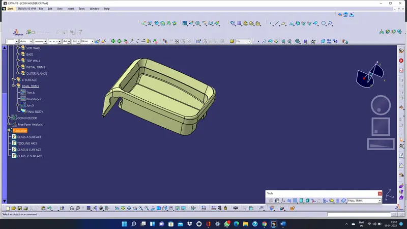
SOLID BODY:
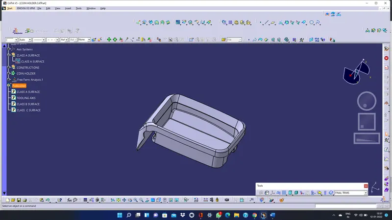
DRAFT ANALYSIS OF A SOLID BODY:
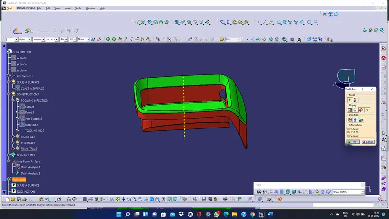
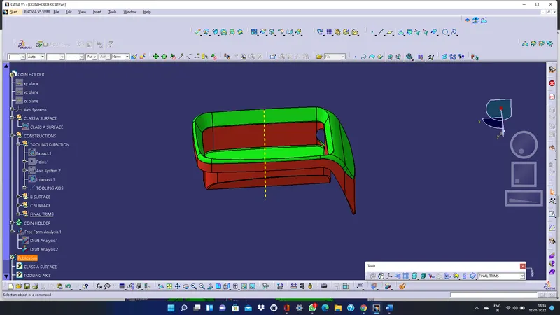

In the given class A surface of coin holder has -3 degree angle for sidewalls because in draft analysis of coin holder it shows that.
CONCLUSION:
Now we Create the Coin Holder Plastic component through the given Class-A surface. To begin with, the tooling axis for the given Class-A Surface should be created meeting the requirements of the draft angle and at the end perform the Draft analysis on the model. Take the Thickness of the component here to be 2.5 mm.