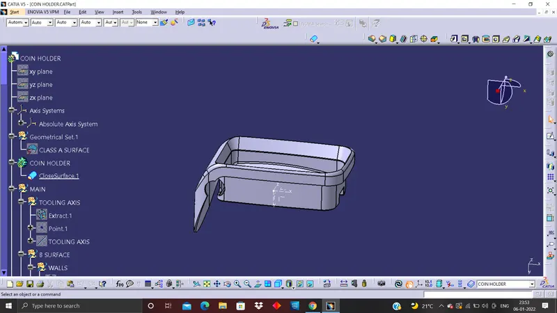
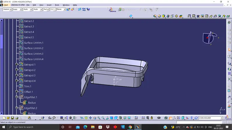
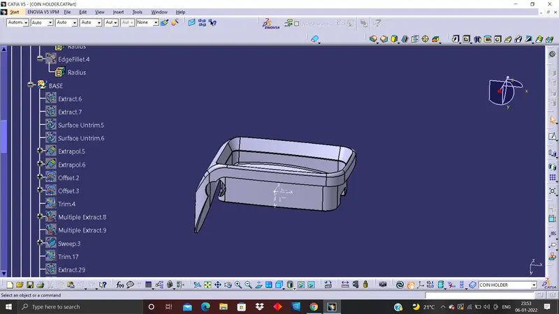
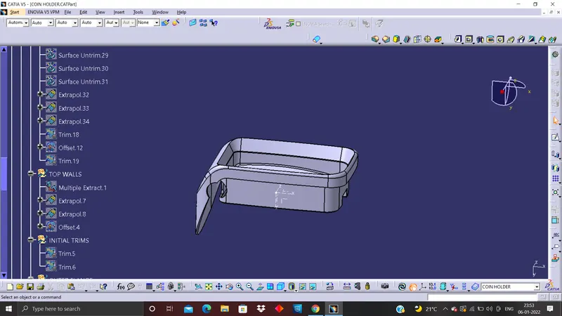
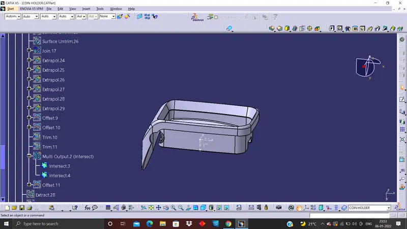
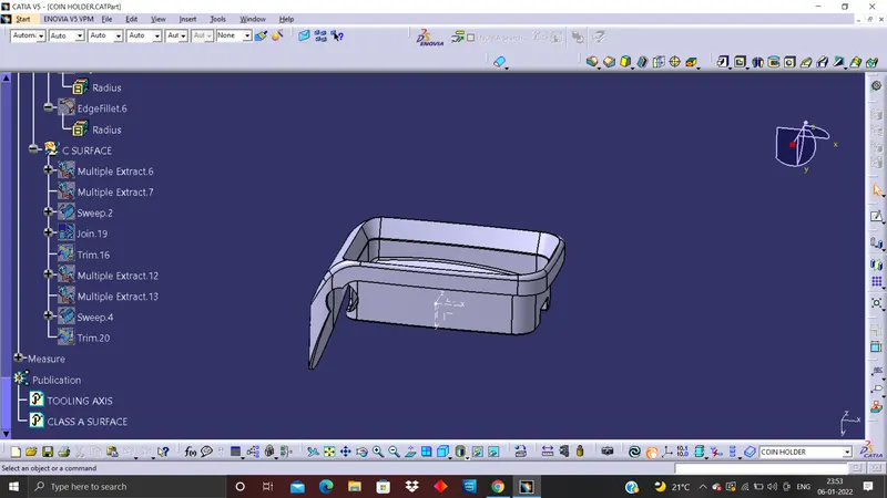
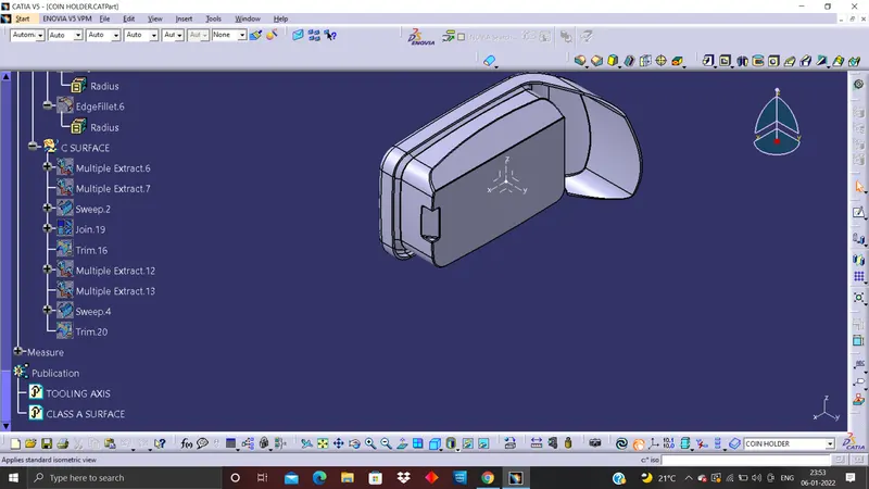
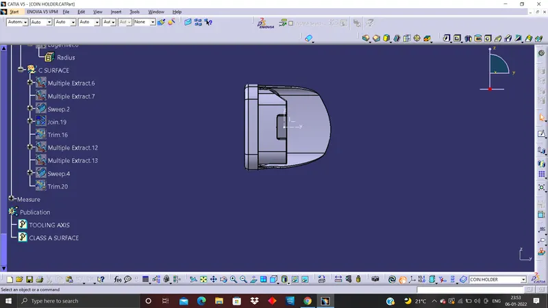
Week 8 - Challenge 4 - Coin Holder Design
DRAFT ANALYSIS OF FAN COVER
A draft angle is a slant that is applied to each side of most features of an injection molded part. The angle, which is positioned to run toward the direction of a mold’s pull and parting line, helps with releasing the part from the mold. It is rare that a component of a part does not need to be drafted. These cases may include certain low-friction materials, such as some grades of nylon, or specific features. However, 99% of the time, you will need to design draft into your part to have the best chance at success with your injection molded part.
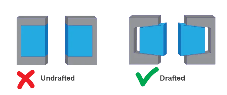
Having easier ejection from the mold may seem like a minor concern, but draft is crucial to manufacturing parts that meet your quality standard. Without draft, major problems can arise in the injection molding process that increase the time and cost of production.
Tooling axis plays major role in creating draft for any design. This acts as a direction of pull in the mold with getting exact component with out disturbing the component.
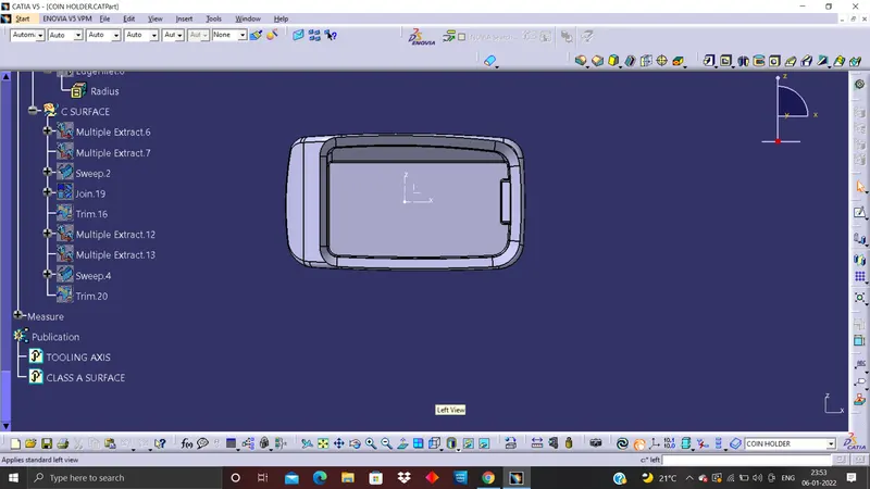
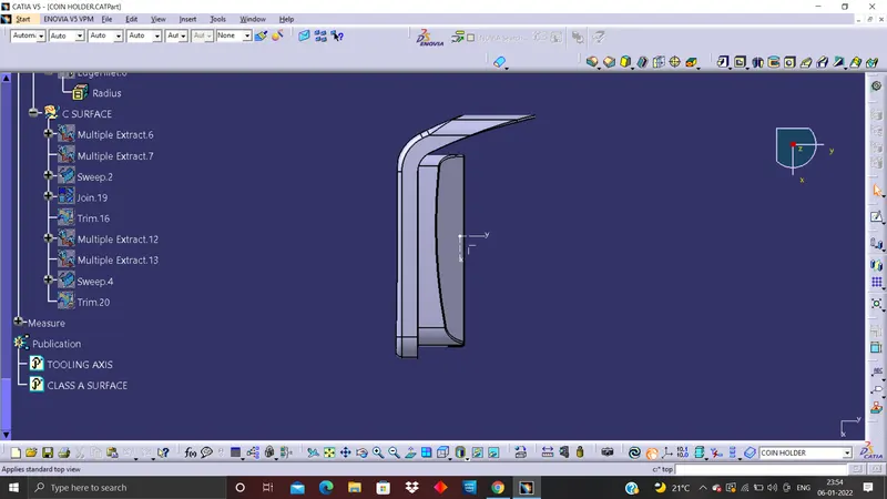
1) first we check the feasability of the design with the help of JOIN command or else Boundary command inorder to verify any gaps with respect to surface.
2) If it is passed we then verify the component complex directions/points in the deisgn and ensure it comes clearly by defining tooling axis.
3) we then create a reference plane inside the part to make section out of it along with YZ plane.
4) We then create line from complicated sections and then create a bisecting line along reference plane.
5) Again create a bisecting line in order to create a MAIN TOOLING AXIS for the design.
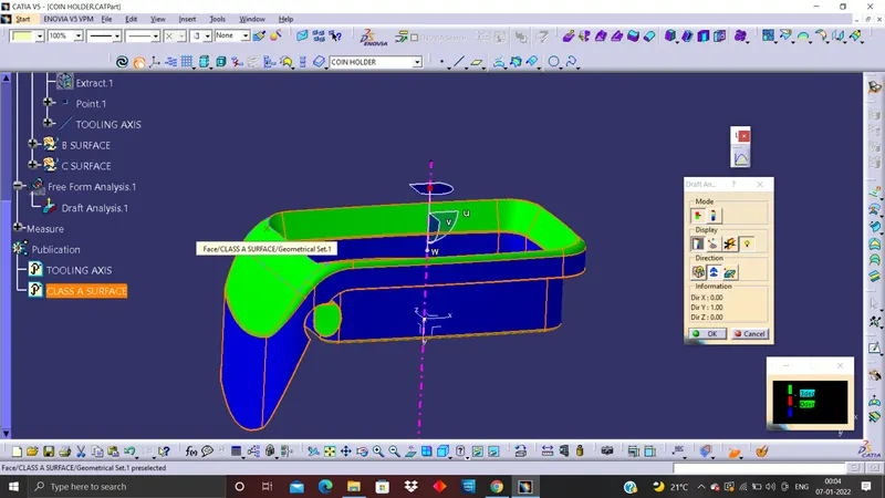
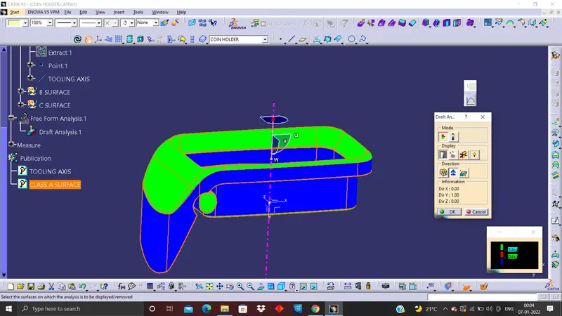
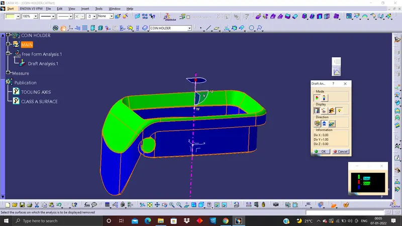
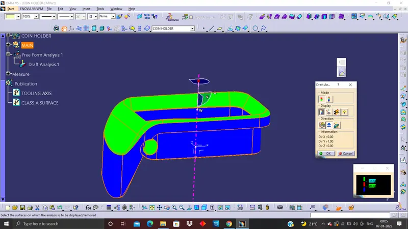
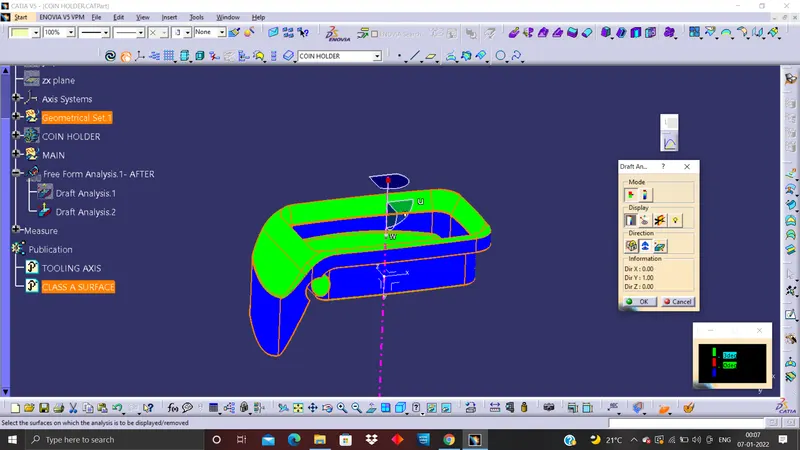
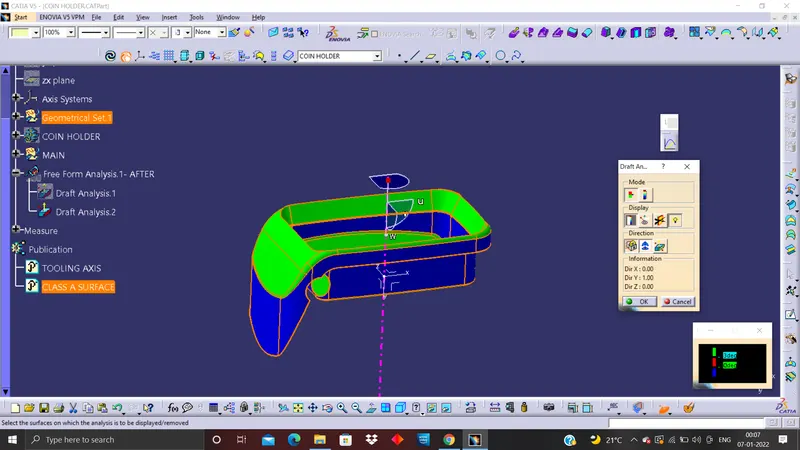
6) after that open Analysis> Feature draft analysis for the next drafting process.(change customize view parameters into material)
7) Use the compass and match the main axis to the tooling axis if deisgn and lock it with lock command
8) Use the light effect and verify the colour intensity of colour.
9) Analysis can also be done with point and also with full analysis mode.