Coin Holder Design
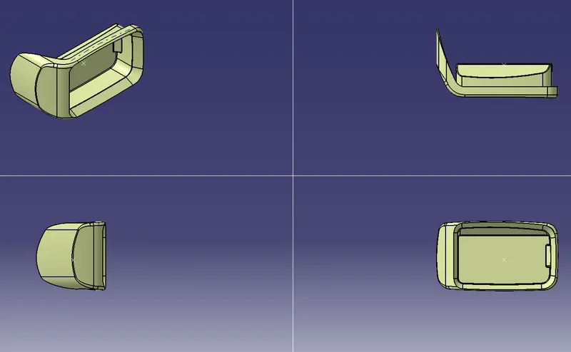
COIN HOLDER
Objective :
- To design coin holder as per automotive OEM Standard.
- Create B Class and C Class and tooling axis.
- Convert close lose the surface into the solid body and provide the thickness of 2.5mm.
- Performing draft analysis to verify the creation of the Tooling axis and C Class surface.
Design Methodology :
Procedure for creating Tooling Axis :
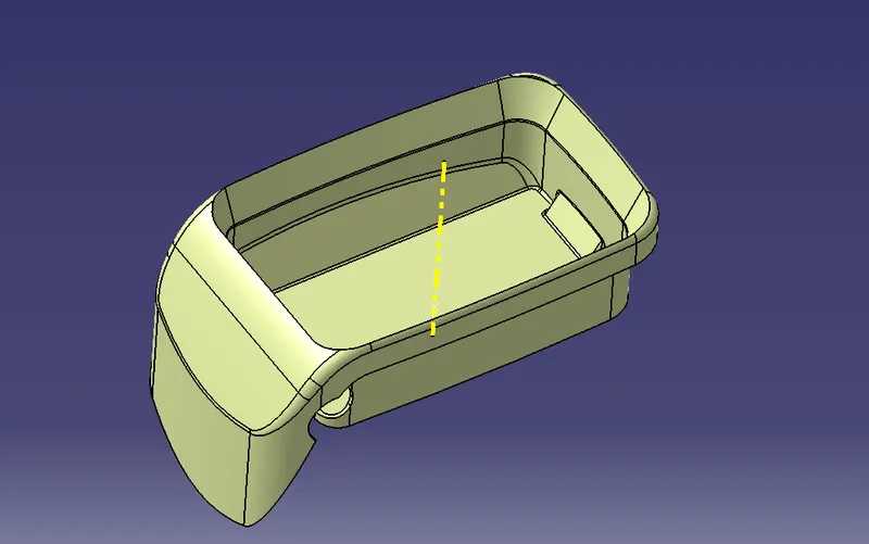
- Intersect the model with the plane perpendicular or to an axis system.
- Extend the lines which are perpendicular to the plane.
- Again intersect the model with another plane and extend the lines perpendicular to it.
- Create a bisecting line by bisecting option in Line definition.
- Rename it as Tooling Axis.
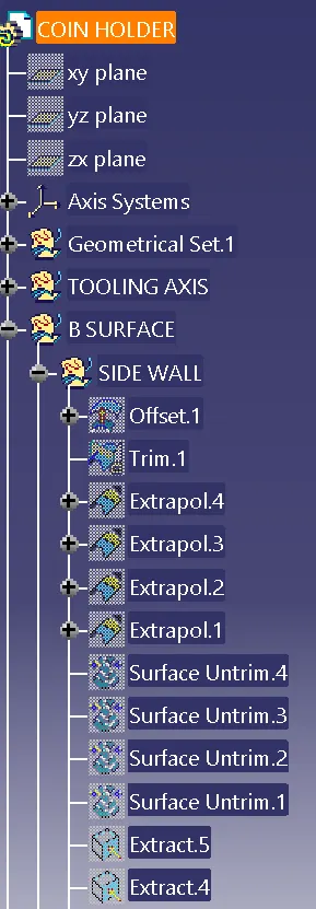
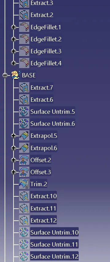
Procedure for creating B Class surafce :
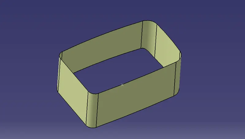
Side Walls:
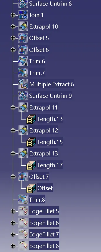
- Extract the side walls with no propagation in extract option.
- Untrim them.
- Extrapolate the walls with point continuity of distance 20mm.
- Trim the walls to get the required shape.
- Offset those trimmed walls with thickness value.
Class C surface creation :
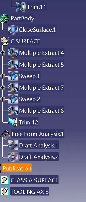
Class C surface for this component is created using sweep command. All the ends of component surface are facing downwards, so the C surface will be created perpendicular to B surface.To create C surface, boundary of class A surface and surfaces adjacent to boundary are extracted. Then sweep with reference surface command is used and surface is created at 90 degree.
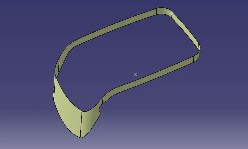
Closed surface :
- Join the Class A and Class C surfaces.
- Trim those joined surfaces with Class B surfaces.
- Go to Part Design and insert a Body.
- Create a closed surface.
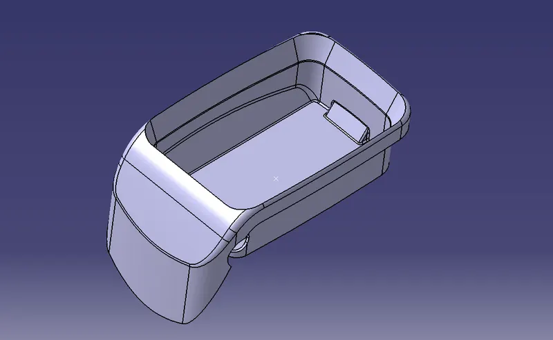
Procedure for creating Draft Analysis:
- Go to the Insert menu and select the Analysis option.
- Select Feature Draft Analysis.
- Select the Material option and select the surface.
- Drag the compass and place on tooling axis.
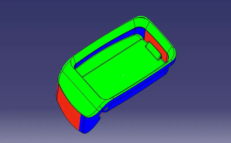
- Make sure that the top surface is in green colour as draft angle should not exceed 3deg.
- Click on Okay after confirm the model.
Draft analysis is performed on class A to check the validity of the tooling axis. During draft analysis, it was observed that bin walls are having 90 degree angle with base. There is no minimum draft given to the walls. Since we are not authorised to make changes in class A surface, we can inform class A designer to give minimum draft to walls.Since we have received this surface, we will continue to design using this class A.
Conclusion :
Draft analysis is done on final component to check manufacturing ability. The walls of the bin are having zero draft angle with tooling axis. This will be ignored since it is given in class A surface.Since we are not authorised to make changes in class A surface, we can inform class A designer to give minimum draft to walls.