Radar Mast & Final Assembly of Yacht
INTRODUCTION:
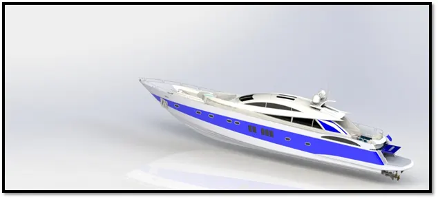
In this project we are to learn the entire modeling of a sun seeker yacht on solid works and solid works visualize.
The different components of the yacht we deal with are:
- Propeller
- Radar
- Blueprint setup
- Hull
- Garage door
- superstructure
- front, rear & middle seats
- Radar mast
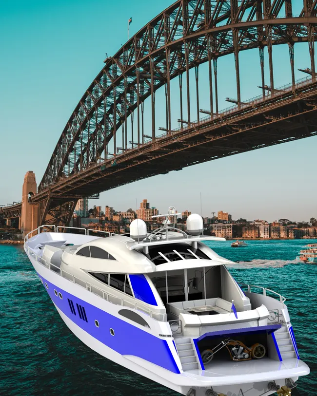
After designing the part components, we have worked upon the assembly and the photo rendering of the yacht which gives it a complete and realistic view.
DESIGN APPROACH:
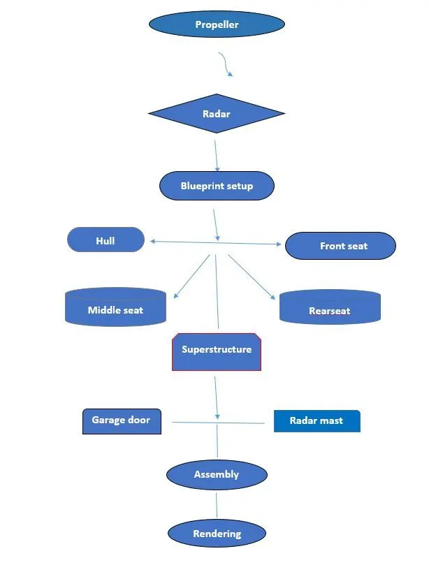
Starting with propeller and ending till the rendering section has been described step by step by means of a flow chart.
Let’s discuss what are the features and properties used in the entire model to design different parts:
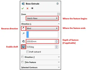
- Extrude Boss: The Extruded Boss is the most basic of all SOLIDWORKS features and extrudes a sketch along a straight-line path to add material. As a sketched feature, it requires a sketch before use. Once the sketch has been created, exit the sketch and select the Features tab of the Command Manager. Then, click the Extruded Boss/Base command. If a yellow dialog box appears in the Property Manager asking you to create a new sketch, don’t worry – simply click on the sketch in the graphics area to use it for the feature. The Property Manager for the Extruded Boss allows you to control starting location, extrude depth and draft for the feature, among several other parameters:
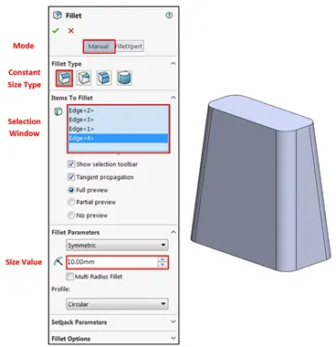
2.Fillet: Fillets are classified as applied features, and as such do not require a sketch to be used. Fillets serve to round off edges and/or corners by adding or removing material, depending on whether the edge is internal or external. It should be noted that fillets of different sizes must be created as separate features. Typically, it is best practice to create the largest fillets first and follow with smaller fillets.
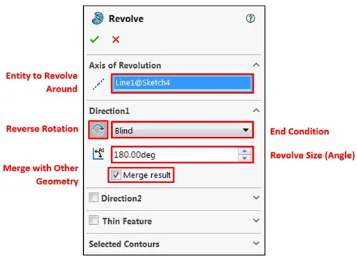
- Revolved Boss Feature: Adds material by revolving a sketch around an axis. Remember, once geometry has been created in your model, any flat face can be used as a sketching surface. It is very important to draw an axis in the sketch which needs to be revolved.
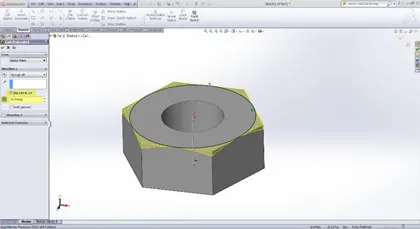
- Extrude Cut: Similar to the extrude boss feature this feature needs a sketch on the solid body which needs to be cut and the desired shape is then cut off.
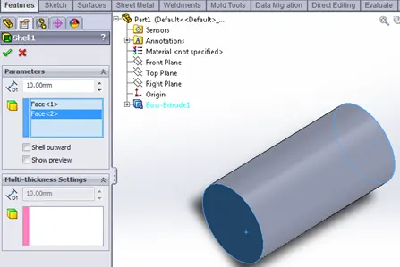
5.Shell: SolidWorks shell tool is mainly used for shelling process, in which the material removed from the inner body of model by keeping small thickness and results a hollow model. Using this tool, you can make either completely closed hollowed model or one face opened type.
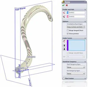
- Sweep Boss / Sweep Cut: Sweep creates a base, boss, cut, or surface by moving a profile (section) along a path, according to these rules: The profile must be closed for a base or boss sweep feature; the profile may be open or closed for a surface sweep feature.
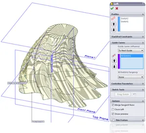
7.Loft Boss/ Loft Cut: The loft feature is an important tool for (surface) modelling in SolidWorks. The loft feature creates a shape by making transitions between multiple profiles and guide curves. This tool is very valuable for modelling complex surfaces. You can do some cool stuff when you use this feature properly.
8.Linear Pattern: You can use linear patterns to create multiple instances of one or more features that you can space uniformly along one or two linear paths. Pattern instances inherit the visual properties of the original feature when you select Propagate Visual Properties in the Property Manager.
|
Seed feature |
Linear pattern - two directions |
|
Linear pattern - one direction |
Linear pattern - two directions Pattern seed feature only in Direction 2 |
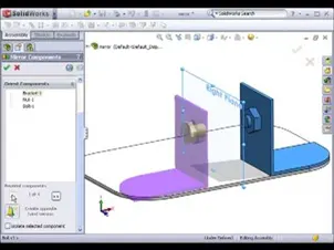
- Mirror: Creates a copy of a feature, (or multiple features), mirrored about a face or a plane. You can select the feature, or you can select the faces that comprise the feature. Bodies to Mirror: Select a body in a single model or multibody part to create a mirror entity. Multibody parts: Apply features to one or more multibody parts by selecting Geometry Pattern and using Feature Scope to choose which bodies should include the feature.
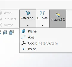
- Reference Geometry: Reference geometry defines the shape or form of a surface or a solid. Reference geometry includes items such as planes, axes, coordinate systems, and points. You can use reference geometry in the creation of several kinds of features. For example:
- Planes are used in lofts and sweeps.
- An axis is used in a circular pattern.
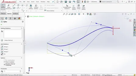
- Projected Curve: You can project a sketched curve onto a model face to create a 3D curve. You can also create a 3D curve that represents the intersection of two extruded surfaces generated by creating sketches on two intersecting planes. You can create multiple closed or open-contour projected curves from a single sketch. You can also use 3D sketches as input for the Projected Curve tool. Note: the Projected Curve tool does not support projections of intersecting curves.
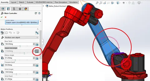
12.Mate: Mates create geometric relationships between assembly components. As you add mates, you define the allowable directions of linear or rotational motion of the components. You can move a component within its degrees of freedom, visualizing the assembly's behaviour.
Some examples include:
- A coincident mate forces two planar faces to become coplanar. The faces can move along one another but cannot be pulled apart.
- A concentric mate forces two cylindrical faces to become concentric. The faces can move along the common axis but cannot be moved away from this axis.
Mates are solved together as a system. The order in which you add mates does not matter; all mates are solved at the same time. You can suppress mates just as you can suppress features.
- Surface features:
The boundary surface feature lets you create surfaces that can be tangent or curvature continuous in both directions (all sides of the surface). In most cases, this delivers a higher quality result than the loft tool.
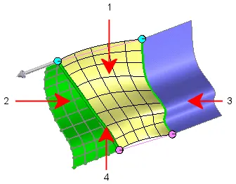
You can create planar surfaces from these items:
- A non-intersecting closed sketch
- A set of closed edges
- Multiple co-planar parting lines
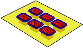
You can create extruded surfaces from models that include 2D or 3D faces and knit the extruded surfaces to surrounding features.
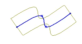
Choose different sketches from intersecting or non-intersecting sketches to create revolve with the Selected Contours pointer.
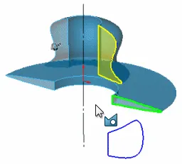
- Create planes for sketching the sweep profile, sweep path, and if necessary, the guide curves.
- Sketch the sweep profile and path on the planes that you created
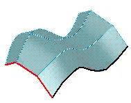
- Create a plane for each profile section of the loft.
- Sketch the section profiles on the planes. You can create all section and guide curve sketches inside a single 3D sketch.
- If necessary, create guide curves
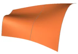
In the Property Manager:
- Select surfaces or faces in the graphics area for Surface or Faces to Offset.
- Set a value for Offset Distance.
You can create an offset surface with a distance of zero.
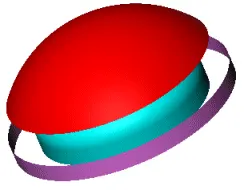
The Radiate Surface tool creates a surface by radiating edges of solids or surfaces along a selected planar direction.
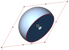
You can cut a solid model by removing material with a surface or plane. With multibody parts, you can select which bodies to keep.
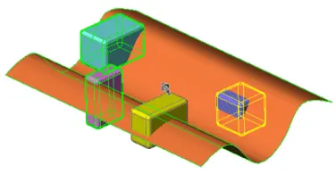
Now as we have completed discussion of how the features work under solid works let us see the application of the features in the Yacht that we have built. We are going to discuss part by part as shown in the flowchart
- Propeller
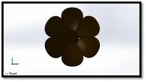
The solid body in propeller a single extruded surface using the revolve and extrude option whose outer edge has been filleted and the appearance used by creating a spline over the solid model and applying circular pattern therefore increasing the number of blades
- Radar
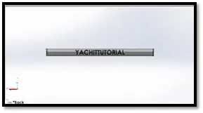
Creating a sketch and then extrude it and then extruding adding the fillet over the round corners and then mirroring the one set of solid body and then adding holes over the face and then add text over the backside of the solid model
- HULL
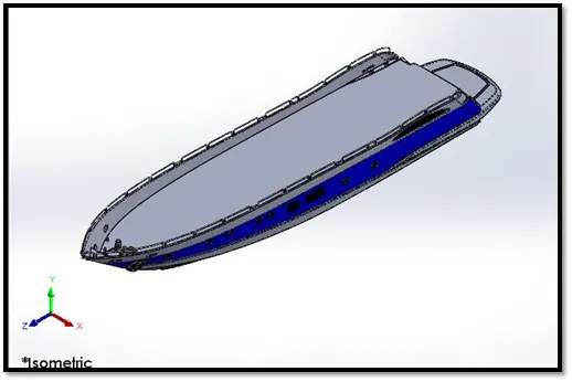
A Hull is a watertight body of a ship or boat. The hull may open at the top or it may be fully or partially covered with a deck. A top of the deck may be a deckhouse and other superstructure, such as funnel, derrick or mast. The line where the hull meets the water surface is called water line. It created by using surface tools and some part of part modelling before that we need setup a blueprint image the list of tools used of hull are mentioned below
- Sketch
- Project curve
- Loft surface
- Fill surface
- Surface Extrude
- Surface trim
- Surface Extend
- Shell
- Boss Extrude
- Cut Extrude
- Fillet
- Chamfer
- Sweep
- Plane
- Dome
- Helix/Spiral
- Linear Pattern
- Delete face
- Combine
- Revolve
- Curve
- Garage door
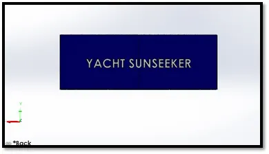
A garage door is a large door on a garage that opens either manually or by an electric motor. Garage door are frequently large enough to accommodate automobiles and other vehicles commands used for garage door
- Sketch
- Extrude cut
- Fillet
- Mirror
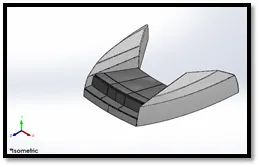
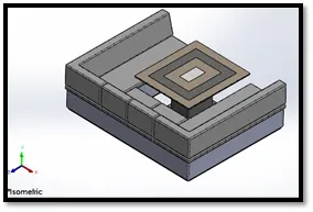
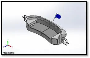
5.Front, middle and rear seats
This is a thing which is used for sitting purpose. The rear seat is built rear side of the yacht list of tools used of modelling seats.
- Sketch
- Surface sweep
- Surface offset
- Surface trim
- Ruled Surface
- Surface knit
- Surface Extend
- Surface loft
- Boss Extrude
- Cut Extrude
- Fillet
- Chamfer
- Mirror
- Revolve
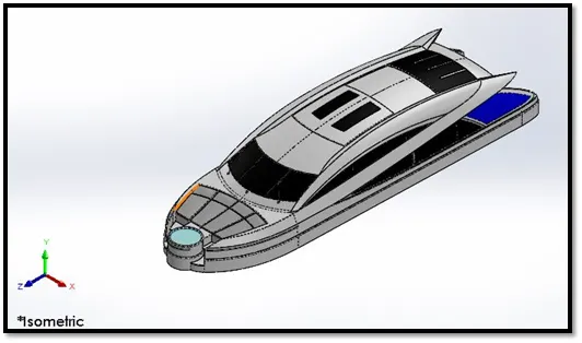
- Superstructure
A super structure is an extended construction of any building or platform that rises above the rest of the building or platform in a distant manner. Thus super structure means to add a construction to an already existing structure. In ships this is the name given to the part of the ship that emerges from the deck.
Commands used in Superstructure:
- Sketch
- Surface extrude
- Ruled surface
- Surface sweep
- Knit surface
- Cut extrude
- Loft surface
- Extrude thin
- Chamfer
- Fillet
- Mirror
- Combine
- Sweep
- Thicken surface
- Dome
- Combine
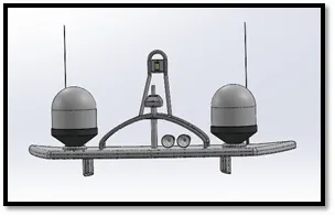
- Radar mast
Radar Mast is a modern ferry. Navigation Mast supporting the ships radar, at front the containers holding inflatable life boats on the side of an ocean. Radar and other instruments on the top of a ship.
Commands used in Radar mast:
- Sketch
- Boss extrude
- Revolve thin
- Sweep
- Dome
- Shell
- Fillet
- Chamfer
- Mirror
- Assembly
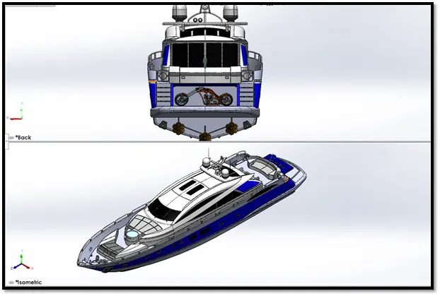
All the modelled parts are inserted one by one in the assembly since the parts are created based on the reference with the deck surface the parts are automatically fixed above the deck surface while the part being inserted in the assembly. So to start the assembly of the yacht the first part being inserted will be the hull which has the deck surface. The propeller, radar, garage door is not fully fixed since they have to rotate and move respectively. So for these parts the mates are manually defined to allow them to move in particular axis.
- Rendering
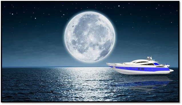
The final step of the yacht to make it look realistic as we have already discuss the uses of rendering a model here we try to make it look as realistic as, now we try to make it more realistic by giving it a camera view setting the desired lights and the focal distance creating the angle of the view and saving the camera angle which gave a realistic view to the yacht. Now we take our assembly file into solid works visualize where we start making the product more and more realistic with adding the background changing the and adjusting the brightness, shadow density and gamma levels according to the different requirements of the different backgrounds changing the color of the model and checking what suits the best with which background until we get the desired and astonishing product ready