Advanced Sheet Metal Design Using NX Cad Casing Design
OBJECTIVE:
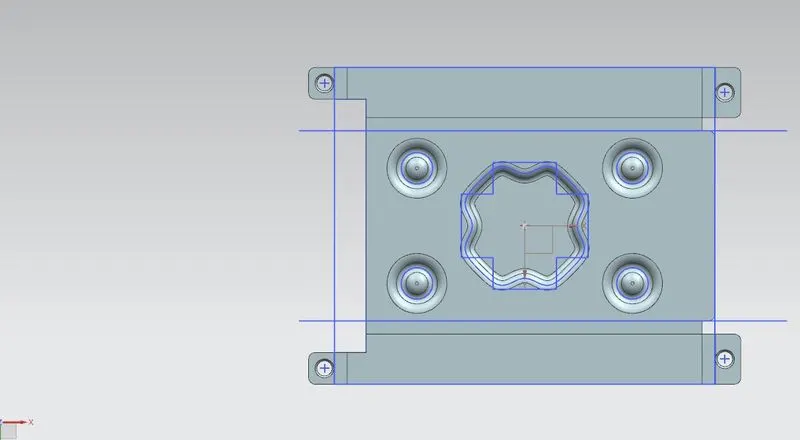
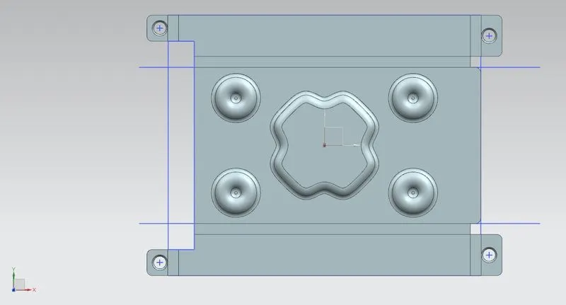
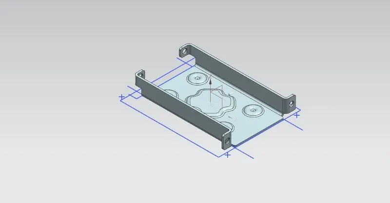
To design a sheet metal casing using NX CAD (sheetmetal workbench)
INT RODUCTION:
The sheetmetal application provides an environment for the design of sheet metal parts used in Machinery, Automotive and Aerospace. Enclosures, Brackets and other parts are normally manufactured with break press. The sheet metal application are widely used in the
- Aircraft Bodies
- Automobiles
- Utensils used for domestic purpose
- Beverage cans
In sheetmatal application we can create a uniform thickeness sheetmetal parts using basic features such as flange, tabs and jogs. We can also do close corners, cutout and stiffening features. The complex sheet metal part can be desinged in the solid model workbench and then we can convert it into a sheet metal part. We can also import, clean up and convert a non sheet metal part into a valid sheet metal part. Flat pattern sheet metal data can be used for the manufacturing process. The Material parameters such as thickness, bend radii and bend relief can be easliy set as default settings.
DESIGINING METHODOLIGIES:
DESCRIPTION:
- TAB - It creates a sheet metal of preferred thickness. create a sketch of rectangle and select TAB tool to create a sheet metal.
- CUTOUT - Cuts out a section of a part with reference to a sketch.
- BENDING - Creating a reference line for bending action which acts as the bend angle for the sheet metal. select BEND tool after the reference sketch lines and using the lines as reference create bend
- FLANGE- Used to create a flange from the stationary part and bends between both and creates and bend flange
- BREAK CORNER -Rounds or chamfers sharp corner edges of a flange or tab. select the tool BREAK CORNER and just click the edges to be chamfered.
- UNBEND - Unbend all the flnages and bends created in a progressive form to repeat in REBEND.
- HOLE - Under design feature more there is HOLE tool which adds hole to any part with preferred type and specification of holes.
- DIMPLE - A tool for stamping feature which represents on a curve sketch for reference. It lifts the material through the sketch marking as a stamping feature.
- BEAD - Another stamping tool features the lifting of material with sketch along the contour
- REBEND - Restores the UNBEND feature along with the bend in the reverse progressive manner of the UNBEND with representing the stationary face or tab.
CONCLUSION:
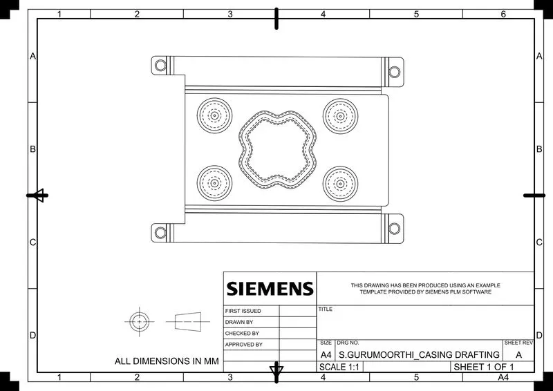
In the NX CAD by the tools and features of the sheet metal workbench SKETCH, TAB, NORMAL CUTOUT, BEND, FLANGE, BREAK CORNER, UNBEND, HOLE, DIMPLE, BEAD, REBEND, DRAFTING we conclude the SHEET METAL CASING DESIGN.
NOTE:The Images and flow chart are attached as document below.