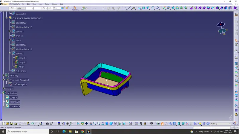
Week 8 - Challenge 4 - Coin Holder Design
AIM :
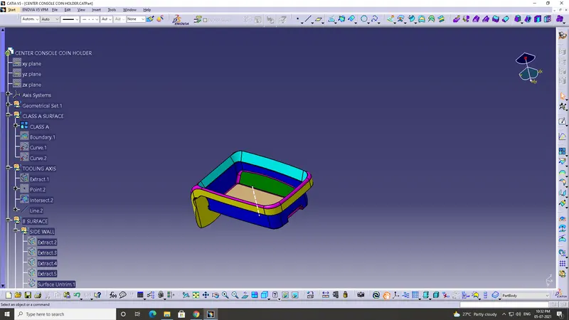
Create the Coin Holder Plastic component through the given Class-A surface. To begin with, the tooling axis for the given Class-A Surface should be created meeting the requirements of the draft angle and at the end perform the Draft analysis on the model.
Take the Thickness of the component to be 2.5 mm
DRAFT ANALYSIS :
- 1ST to check the connectivity of the class A surface.
- Ensure that there is no gap between the component, using join command .
- We can visually check it or by clicking boundary command.
- After that disassembled
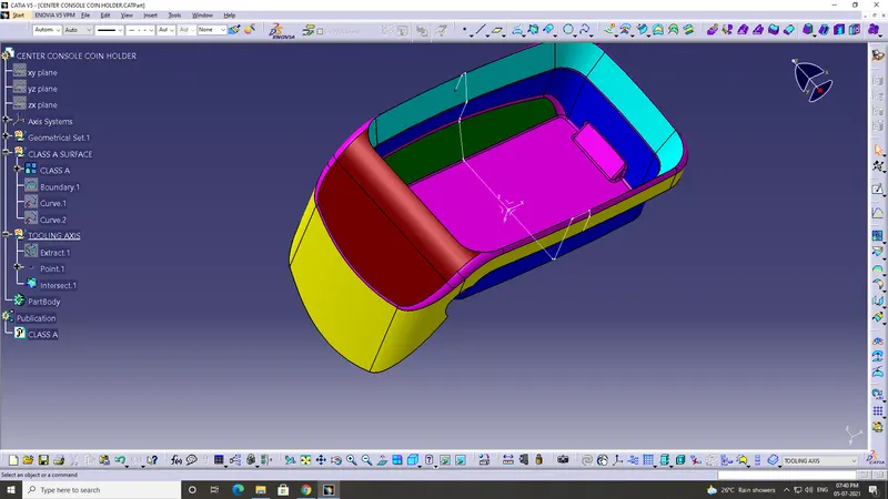
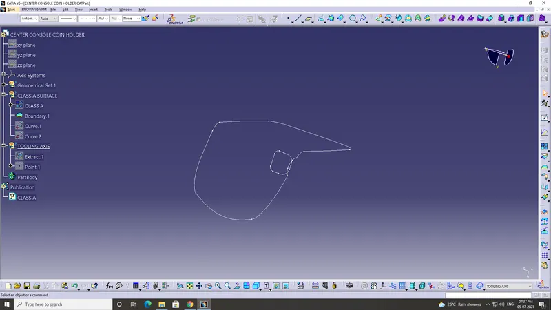
It has 2 boundary. inner and outer.
-
so the 1st design check is completed.
step 2: Find the toling axis of the component.The tooling axis is nothing but the mould opens or cavity opens.
- Check visually which is the best possible tooling direction.
- check all the 3 axis.
- insert the sketch along yz plane.
- intersect of the class A.
now this is the draft analyst tool.
And next place the axis and lock it.
It displayed in green color.
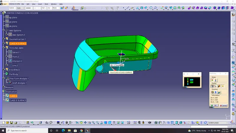
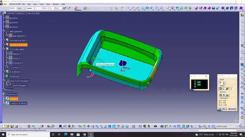
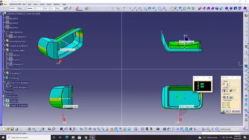
Give boundary and disassambled and give domian 2 only
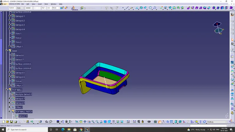
Create a geometric set and name as B SURFACE ------ SIDE WALL SURFACE.
Extract the ALL four side surface without the fillets and give no propagation.
untrim the surface.
Extrapolate 20 mm with point continuity.
trim it.
Hide the extract.
and give the offset value of 2.5mm.
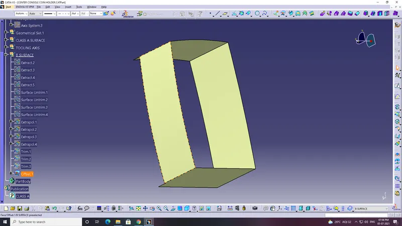
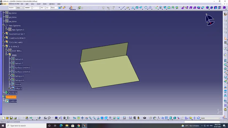
After that create apropretae for all side wall and tha base
Extract the all side walls and give no propagation.
untrim the surface.
Hide the extract.
and give the offset value of 2.5mm.
Extract the base and give no propagation.
untrim the surface.
Hide the extract.
and give the offset value of 2.5mm.
as same as above and trim it.
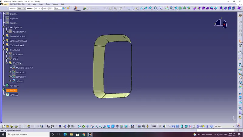
Now to give the fillet for thar measure it.
AFTER THE FILLET INSERT THE GEOMETRIC SET.
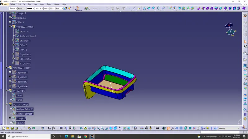
B SURFACE ------ SIDE WALL
Measure it
R - 9,10,17,16
give the appropriate value + 2.5 mm thickness
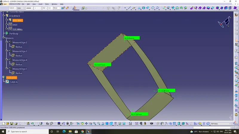
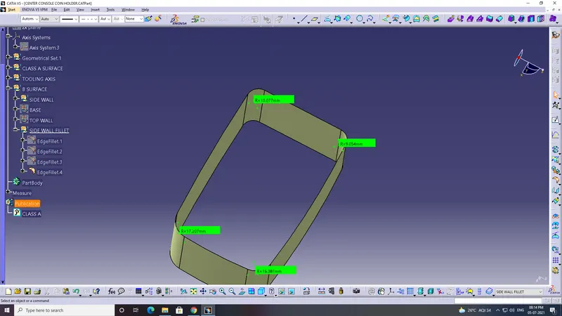
AFTER THAT INSERT THE GEOMETRIC SET.
Intial trim
trim all the component shapes.
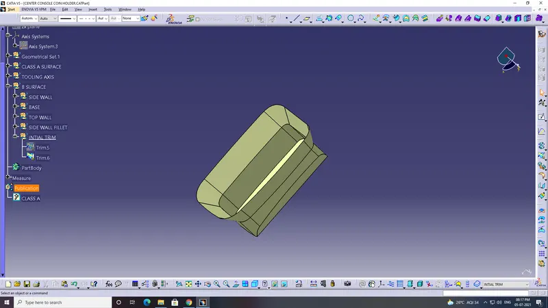
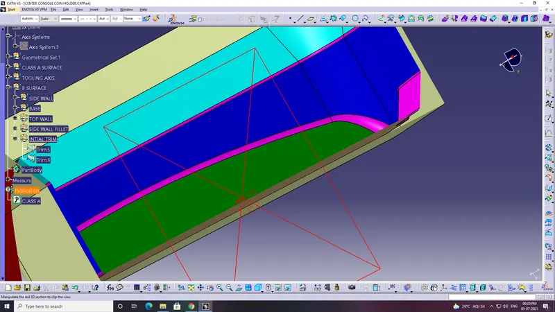
AFTER THAT INSERT THE GEOMETRIC SET.
OUTER FLANGE
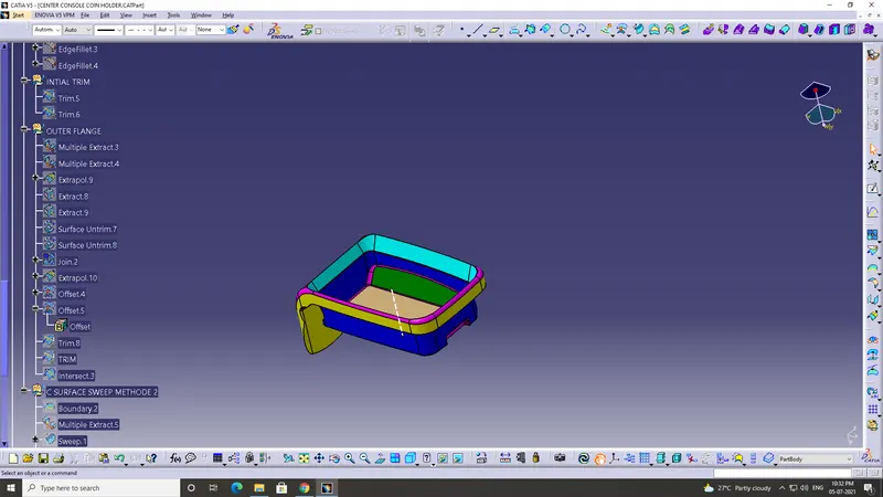
Extract the ALL OUTER FLANGE give no propagation.
untrim the surface.
Extrapolate 10 mm with point continuity.
trim it.
Hide the extract.
and give the offset value of 2.5mm.
AND TRIM IT.
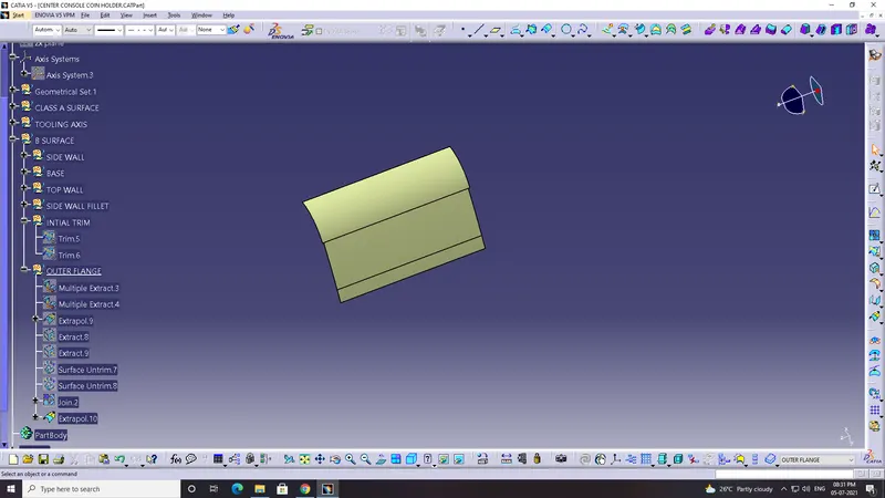
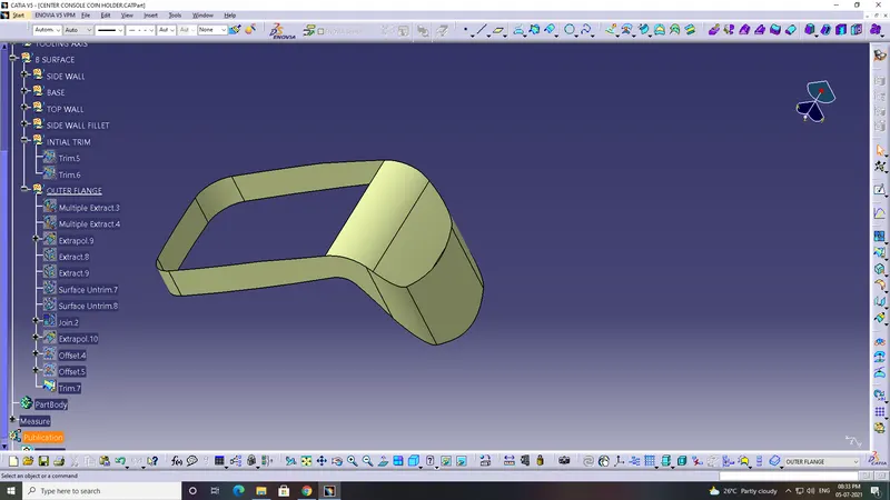
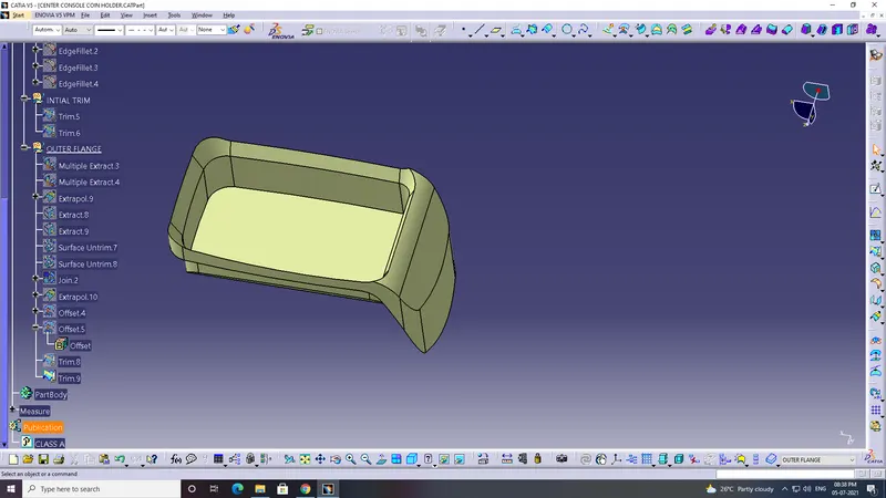
THIS is the B surface.
AND now create c surface.
Give the class B intersection along yz plane.
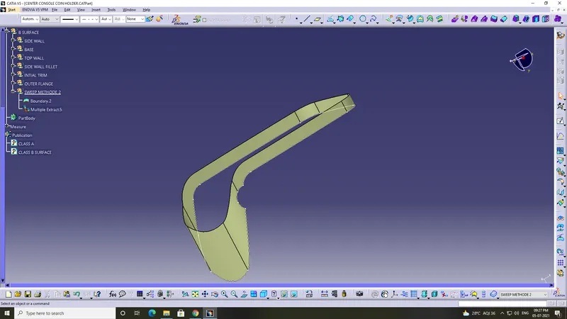
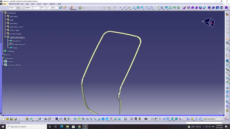
sweeep methode 2.
boundary
and give multiple extract.
and give sept.
give sweep command. ensure that in profile type in 2nd one.
subtype ---- with reference surface
G.C ------ boundray.
reference : multple extract
angle : 90
length : 1mm
since the thickness is 2.5 mm so give the extra 1 or 2mm.
now it is c surface
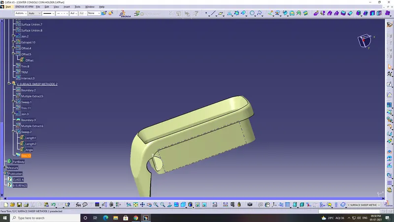
trim the seep and b surface
and now join the class A and C surface.
After that this surface is gonna use it for the closed surface.
so give this surface as the closed surface.
and check it.
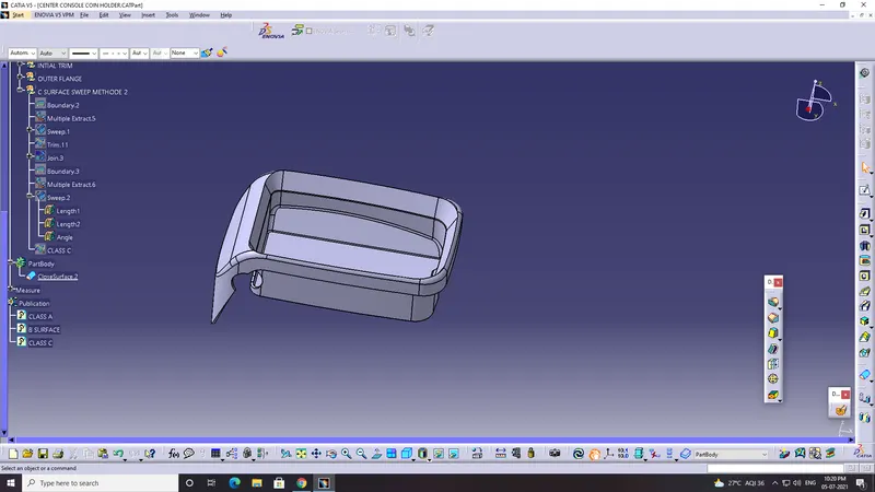
and publish the
- CLASS A SURFACE.
- TOOLING AXIS.
- CLASS B SURFACE.
- CLASS C SURFACE.
- CLOSED SURFACE.

FINAL COMPONENT DRFAT ANALYSIS
now this is the draft analyst tool.
And next place the axis and lock it.
It displayed in green color.
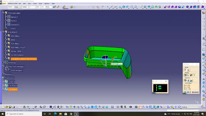
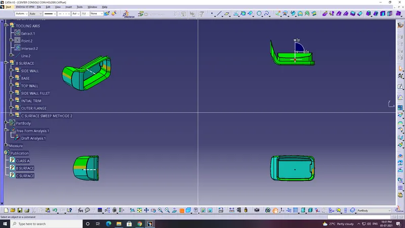
- Screenshots of the expanded Tree Structure for the Geometrical Sets and the Part Body.