Week 8 - Challenge 4 - Bumper
Challenge 4 - BUMPER
Create the Bumper Plastic component through the given Class-A surface. To begin with, the tooling axis for the given Class-A Surface should be created meeting the requirements of the draft angle and at the end perform the Draft analysis on the model.
Take the Thickness of the component to be 3 mm
CLASS-A-SURFACE :
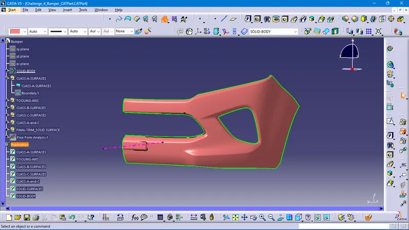
To check the continuity of the class A surface. This is to ensure that there is no gap between the surfaces. If we find any gap, then we should fix that first.
Class-A continuity check
Study the class A surface through visual inspection.
To make sure that the given surface has no gap between them. We can also check it with the help of Join or boundary commands.
TOOLING-AXIS-CREATIONS:
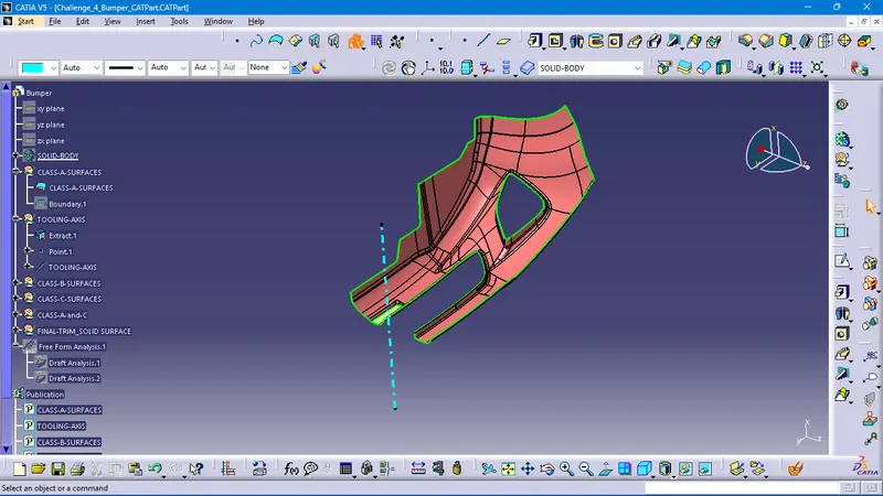
The tooling axis represents the opening and closing of the mold core and cavity during the manufacturing of the components. An injection mold components designer should consider the best tooling direction to cut down the cost of the component very less.
Tooling axis for the bumper
We can find out the best tooling direction by cross-checking all three axes.
Here we can find out that the best tooling direction for the pumper class-A surface is along the x-axis direction
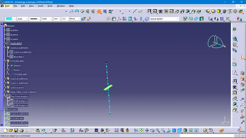
The method I choose to create the tooling axis is first to extract a surface and create a midpoint on that surface. They introduced an axis system at that point.
Then created a with the point and direction along the x-axis.
Here both the outer flanges have a 5.1-degree draft concerning the axis created. Hence going with the axis created will not make any difficulties during the draft analysis.
CLASS-B-SURFACE-CREATIONS
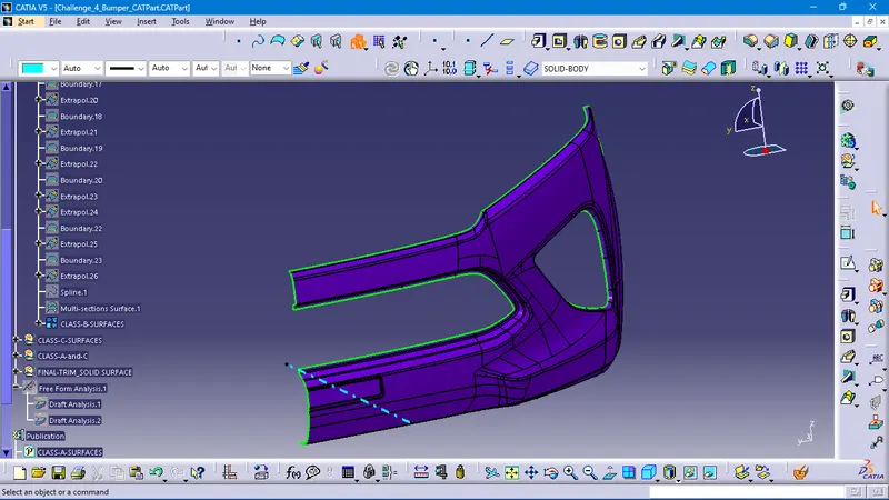
first offset the class-A surface by 3mm inward directions, as they have given the plastic component thickness
if found open surface on the B-Surfaces, should Rework the class-A surfaces. there are three patch surfaces found on the class-B surfaces. to remove the patches by using the given command to rework the patched surfaces
Join, disassemble, Boundary, Extrapolated, trim, spline, Multisection surface, and edge fillet.
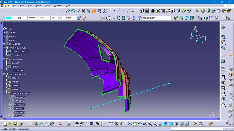
CLASS-C-SURFACE-CREATIONS
To create the class-C surface, unhide the class-A- surfaces to create the boundary surface on the edge, then,
Classified the sweep operation to perform in the right approach,
If the surface edges are perpendicular to the Tooling axis then we have to choose a sweep-reference surface with 90 Degrees to perform the class-C surfaces in the correct directions.
If the surface edges are parallel to the Tooling axis then we have to choose a sweep-draft surface with 3 Degrees to perform the class-C surfaces in the correct directions.
If you find the open edges, use the extrapolate, Boundary, and trim commands to create the perfect class-C surfaces.
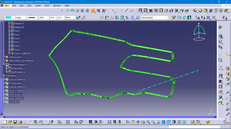
CLASS-A-and-C_SURFACE-CREATIONS
After the class-C surface creations, join the class-a surface to class-c- surfaces. by using the Join command.
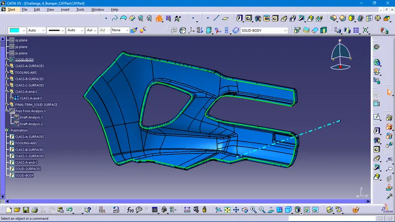
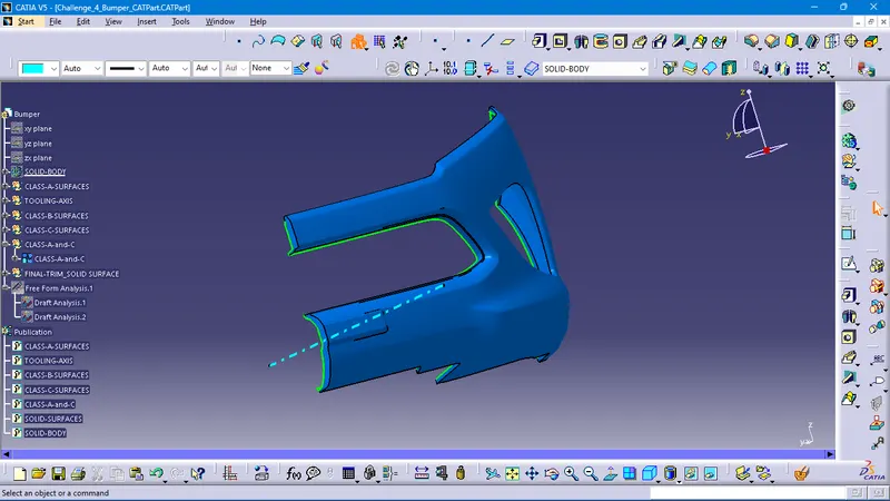
FINAL TRIM TO MAKE SOLID SURFACES.
By using the Trim, command, remove the unwanted surfaces and closed surfaces to create a solid surface of the plastic components.
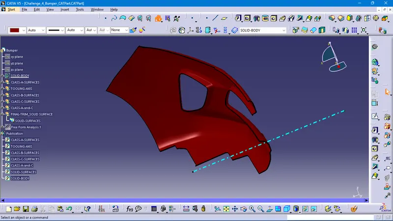
DRAFT ANALYSIS For CLASS-A-SURFACE
The Draft Analysis is a command that enables you to detect if the part you drafted will be easily removed. This type of analysis is performed based on color ranges identifying zones on the analyzed element where the deviation from the draft direction at any point, corresponds to specified values.
Draft analysis is done after determining the tooling axis, draft analysis is used to check whether the minimum draft (3 degrees) is maintained or not.
The procedure for performing the draft analysis
Change the view mode of the component to be in customized parameter mode and then select the shading mode as materials.
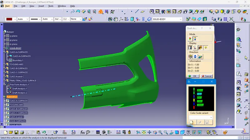
Then select the compass to define the current drafting direction and then drag and align the compass on the Tooling axis.
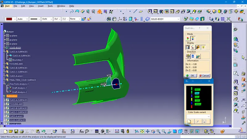
DRAFT ANALYSIS For SOLID-BODY
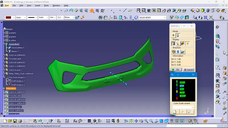
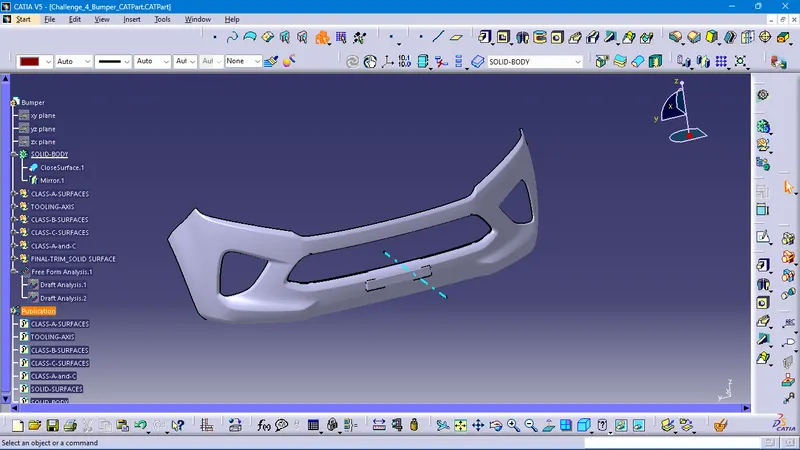
select the part design to perform the closed surface body, by using the closed surface command, and use the mirror command to get the full Bumper surface to perform the final plastic body draft analysis.
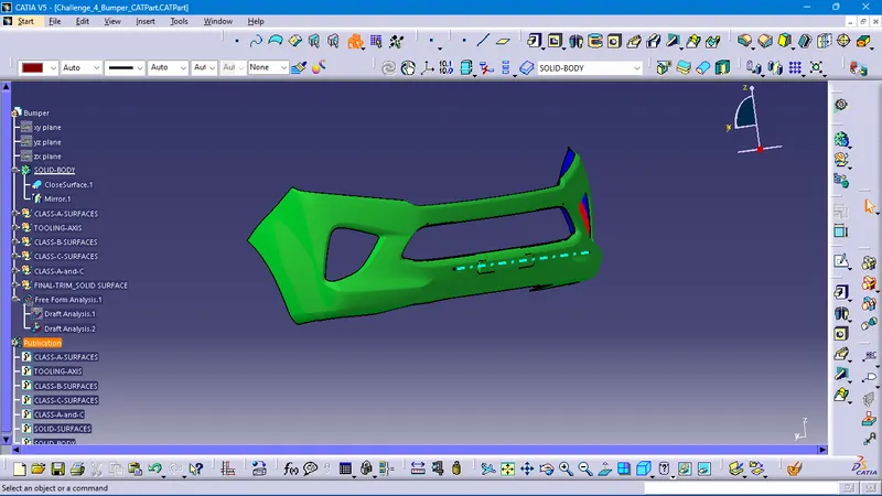
SOLID-BODY-CREATIONS
Select the part design to perform the closed surface body, by using the closed surface command, and use the mirror command to get the full Bumper surface
please refer to the attached file for your review in detail.
Thanks
Regards
sathish