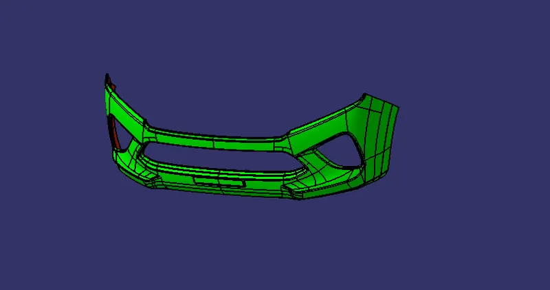
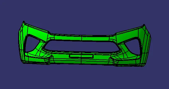
Week 8 - Challenge 4 - Bumper
Report
Tooling direction- The Tooling Direction is the direction in which the mold pulls apart. The mold is built in two separate pieces, basically. You have a Cavity side and you have the Core side. The Core pulls apart from the Cavity and that's the Dyeline or the Tooling Direction.
Creation of tooling axis
Bisecting method
- Take a good look at the Class A surface and find the tooling direction. If there is a hole in the class A surface start from that. consider a dummy tooling axis perpendicular to that hole.
- if the is no hole then rotate the class A surface in different views so that you can find a good view of all surfaces in the particular view.
- after you identified the tooling direction create a dummy tooling axis with the help of surface extraction or point. the line must be in the direction of the tooling.
- create an intersection of Class a surface they find the lines that may create problems during manufacturing.
- draw the lines intersecting with these lines
- then draw a line that bisects these lines
- and perform this process in both X-Y directions. so at the end of this, you got 2 lines
- final step is to create a bisecting line between them
Draft analysis- Draft analysis is a common tool used in CAD (computer-aided design) software to determine the angles of sloped surfaces in a 3D model. The purpose of the draft analysis is to identify surfaces that do not have a uniform angle of inclination or draft angle, which can cause manufacturing and production issues in processes like injection molding, casting, or stamping.
steps
- open the CAD you want to do draft analysis on
- put materials option active inside customize view
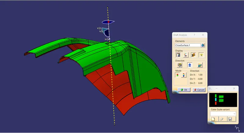
- Then navigate the draft analysis (insert - analysis - draft analysis)
- Drag the compass and place it over the tooling axis
- select the compass option in the draft analysis and place it over the tooling axis
- select the part anywhere
- the appearance of that part will change
- it shows the colors for the draft
- green -ok (means the value you set for the draft is ok in the tooling. part can be manufacturable) Ex 3 deg
- Red - less than the given draft ( less than 3deg, greater than 0deg)
- Blue - not able to draft. the draft is negative (less than zero)
color is for representation we can change them according to our preference
Tooling Axis & Draft analysis
for this particular, I go with a different method ( I go with inertia and find the point and I visibly check the tooling direction and the tooling direction is in the x direction so I crate line intersecting with the point I create in the X direction
class A surface
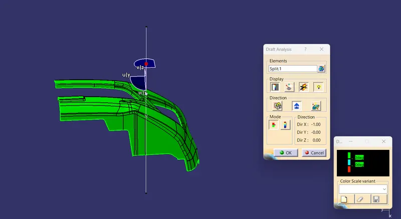
for the plastic body
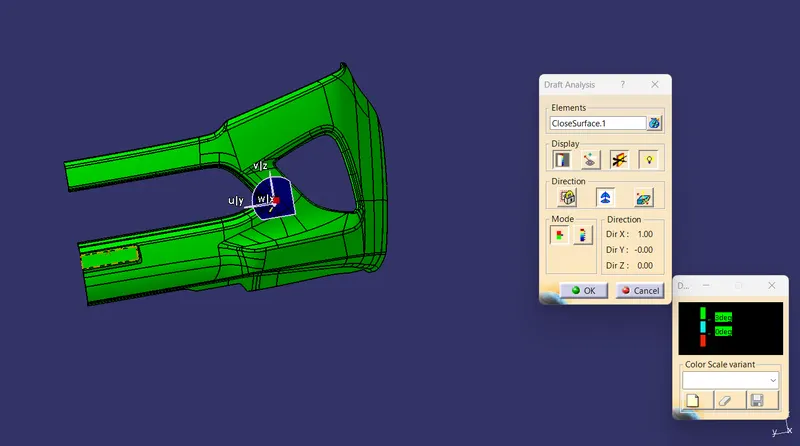
Class B Surface Creation
Class A
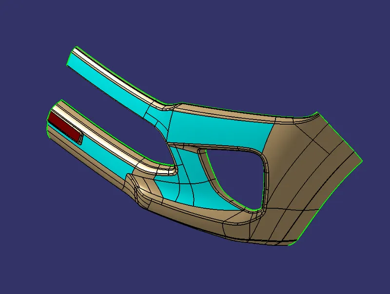
offset 3mm
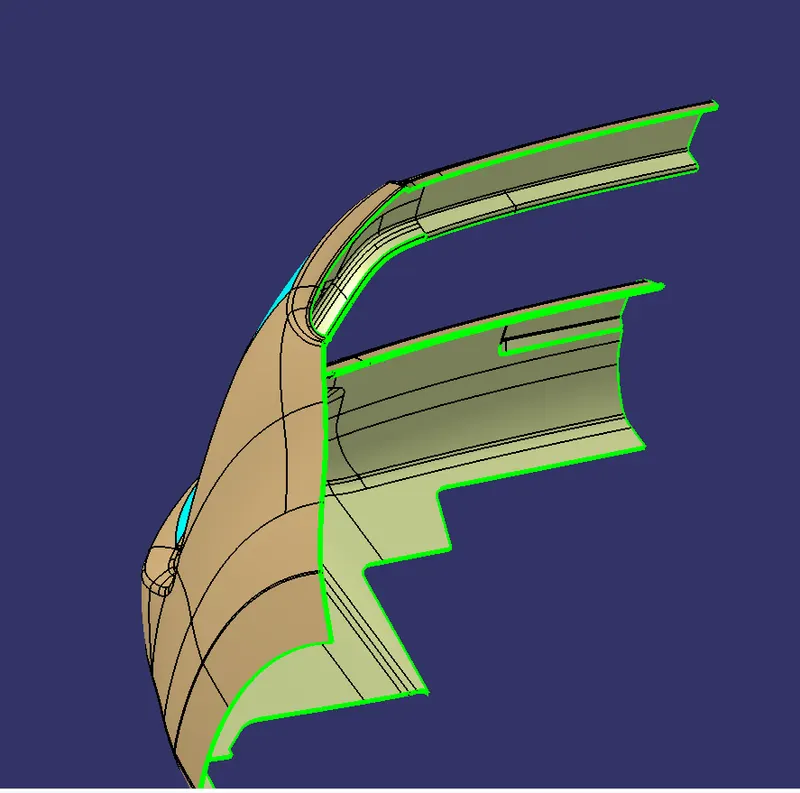
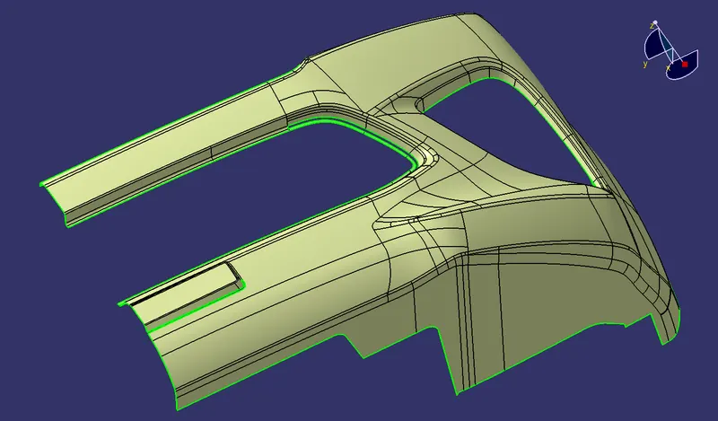
multisection extract (complimentary mode)
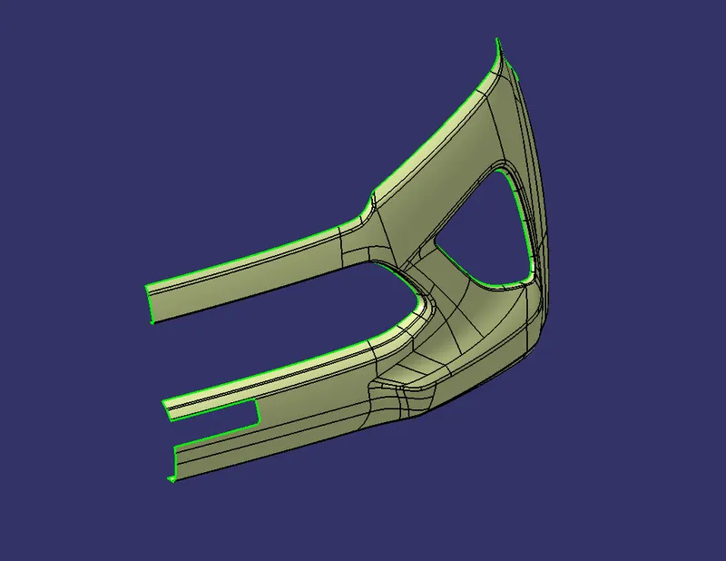
multisection extract
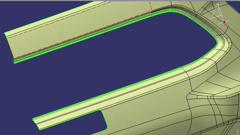
offset & extrapolate radiator grill
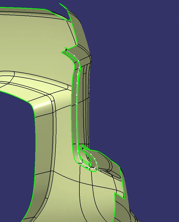
trim
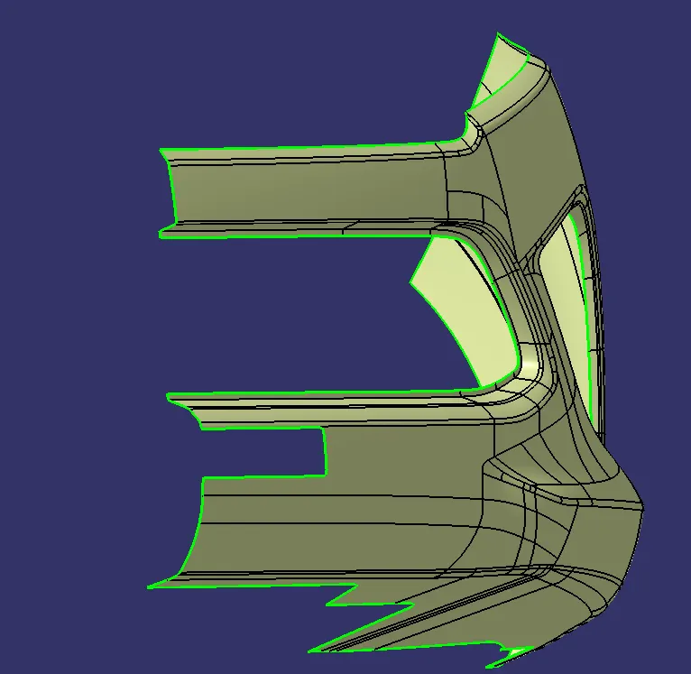
number plate
multisection extract
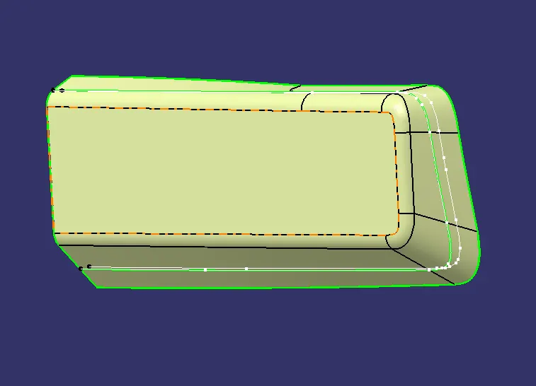
offset
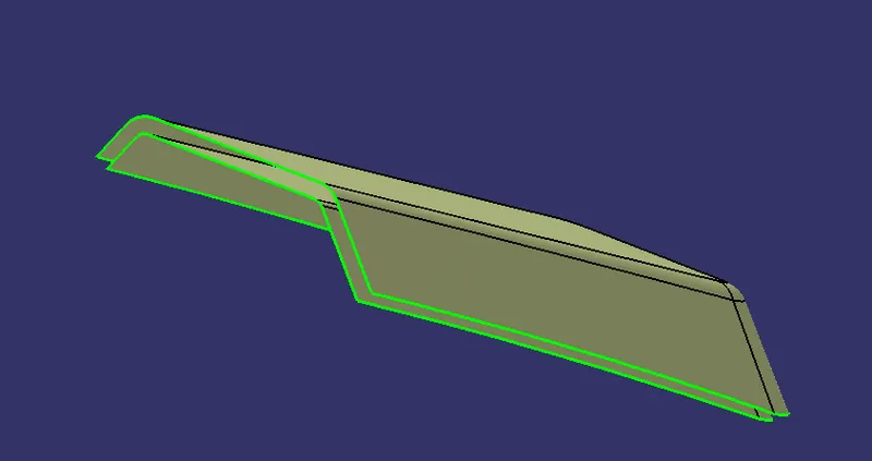
extrapolate
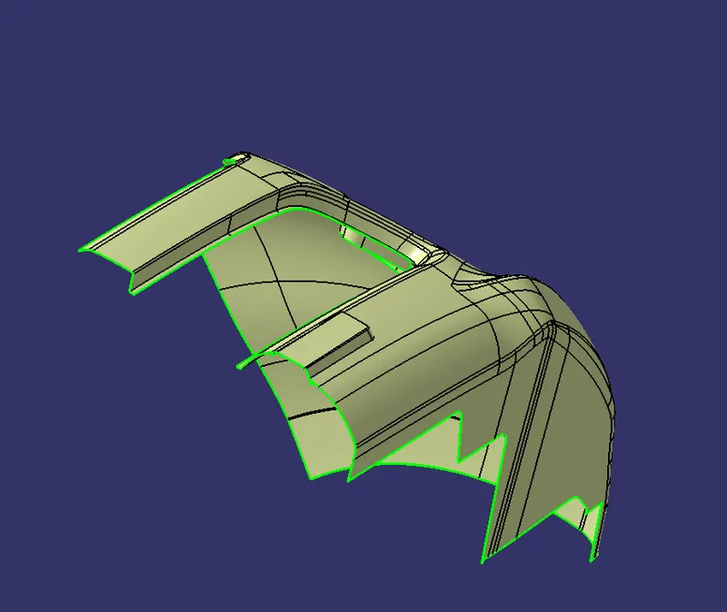
trim
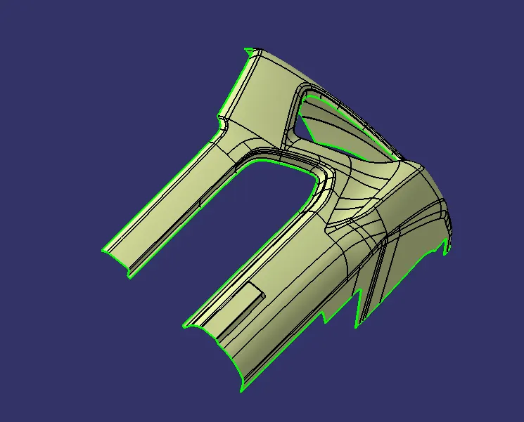
Bonet layer
extation
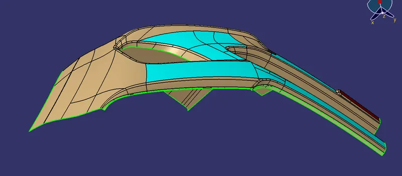
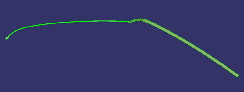
offset
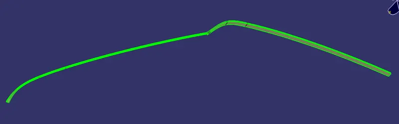
extrapolate
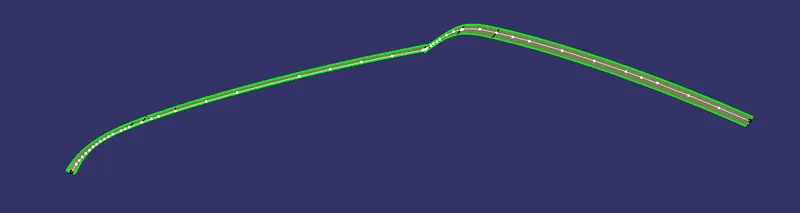
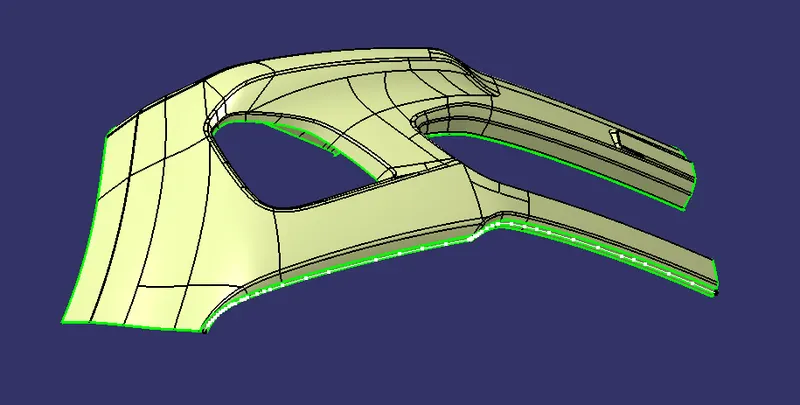
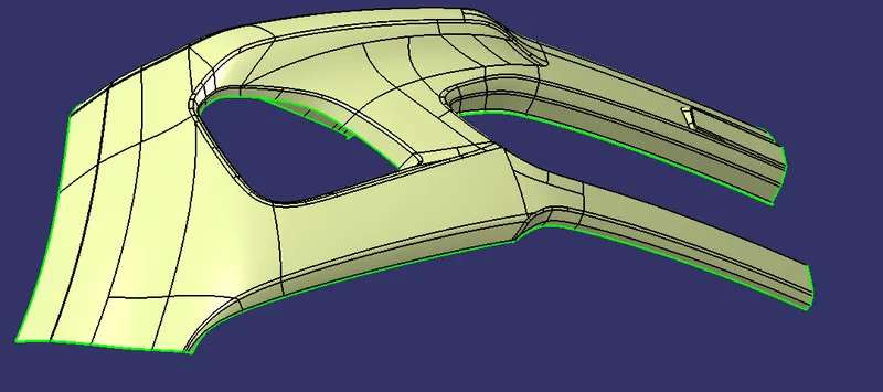
extrapolate
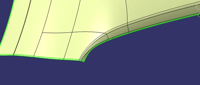
fillet identification
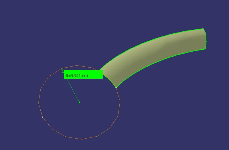
fillet apply
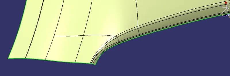
extrapolate
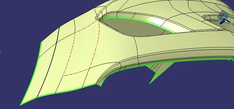
Class C Surface
boundary + sweep (5mm at 90 deg) + join all sweep together
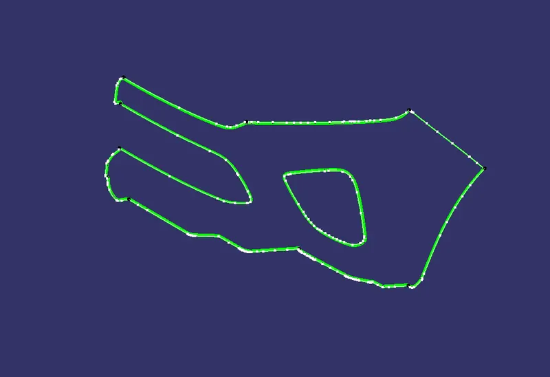
joining Class A to Class C
the problem facing during joining
[ there is some area that has a couple of gaps (more than 0.003mm) so the joining is not performing. so checked with surface intersecting and I find the area where I found the gap so I extrapolate those areas and perform the trim operation with extrapolated Class C surface]
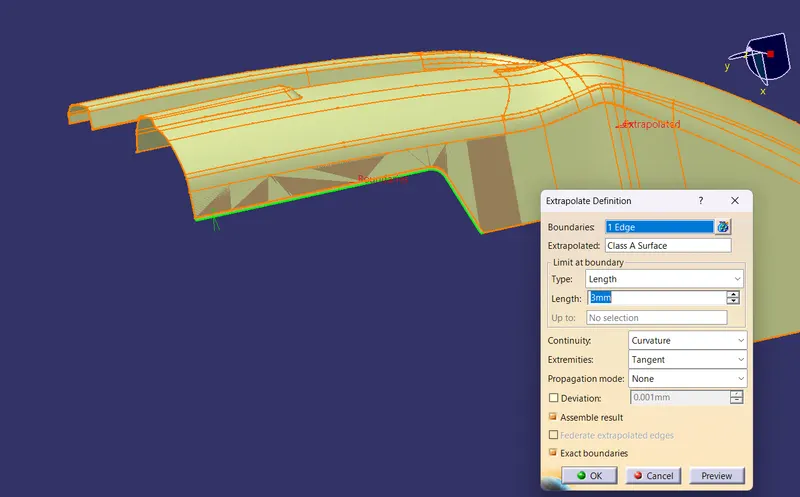
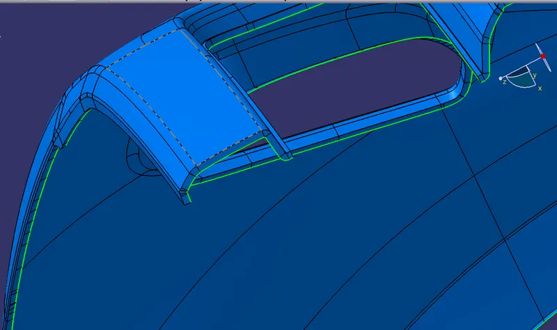
final trim
A+B+C
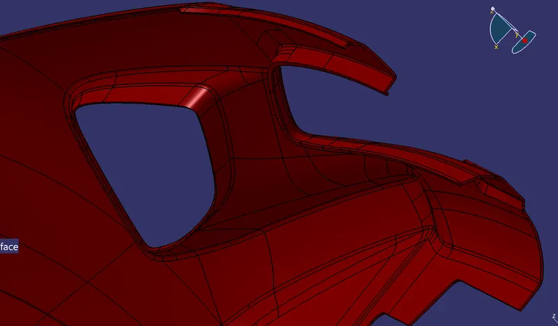
tree
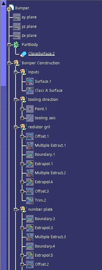
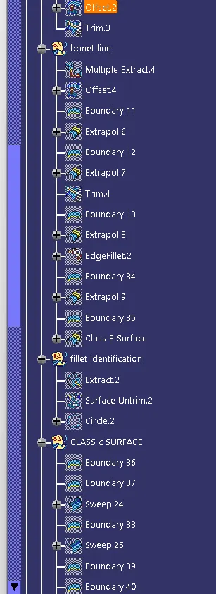
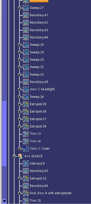
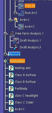
isometric view
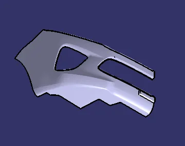
front
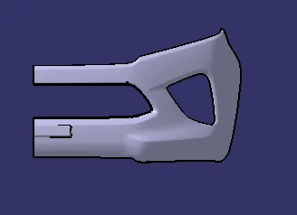
side
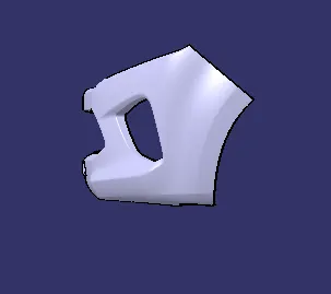
top
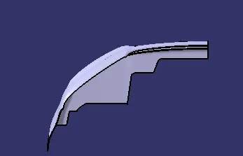
complete