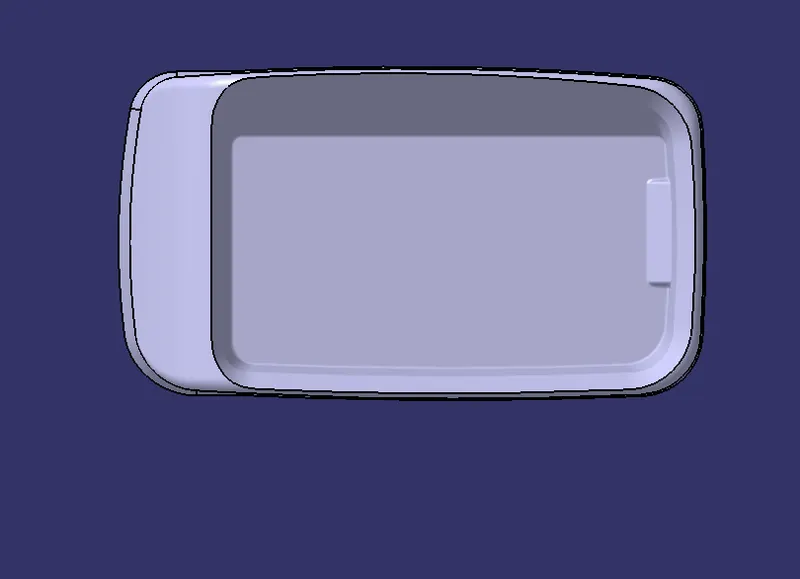
Week 8 - Challenge 3 - Coin Holder Design
Report
Tooling direction- The Tooling Direction is the direction in which the mold pulls apart. The mold is built in two separate pieces, basically. You have a Cavity side and you have the Core side. The Core pulls apart from the Cavity and that's the Dyeline or the Tooling Direction.
Creation of tooling axis
Bisecting method
- Take a good look at the Class A surface and find the tooling direction. If there is a hole in the class A surface start from that. consider a dummy tooling axis perpendicular to that hole.
- if the is no hole then rotate the class A surface in different views so that you can find a good view of all surfaces in the particular view.
- after you identified the tooling direction create a dummy tooling axis with the help of surface extraction or point. the line must be in the direction of the tooling.
- create an intersection of Class a surface they find the lines that may create problems during manufacturing.
- draw the lines intersecting with these lines
- then draw a line that bisects these lines
- and perform this process in both X-Y directions. so at the end of this, you got 2 lines
- final step is to create a bisecting line between them
Draft analysis- Draft analysis is a common tool used in CAD (computer-aided design) software to determine the angles of sloped surfaces in a 3D model. The purpose of the draft analysis is to identify surfaces that do not have a uniform angle of inclination or draft angle, which can cause manufacturing and production issues in processes like injection molding, casting, or stamping.
steps
- open the CAD you want to do draft analysis on
- put materials option active inside customize view
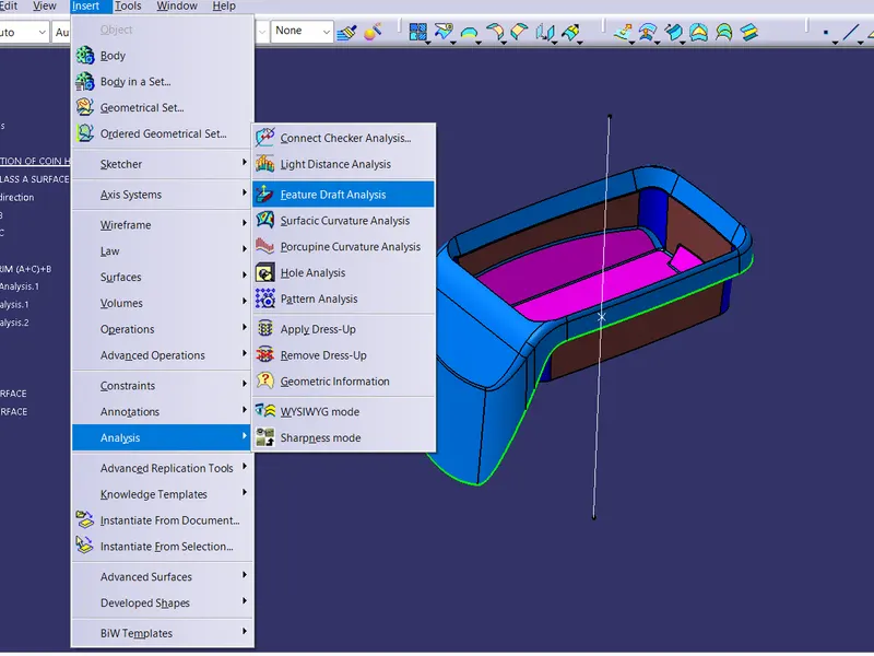
- Then navigate the draft analysis (insert - analysis - draft analysis)
- Drag the compass and place it over the tooling axis
- select the compass option in the draft analysis and place it over the tooling axis
- select the part anywhere
- the appearance of that part will change
- it shows the colors for the draft
- green -ok (means the value you set for the draft is ok in the tooling. part can be manufacturable) Ex 3 deg
- Red - less than the given draft ( less than 3deg, greater than 0deg)
- Blue - not able to draft. the draft is negative (less than zero)
color is for representation we can change them according to our preference
creating the tooling axis by Bisecting method for Week 8 challenge 3
tooling axis creation
Base surface extracted and create a point on the center of the surface
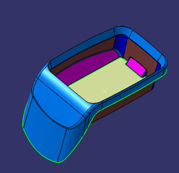
surface intersection
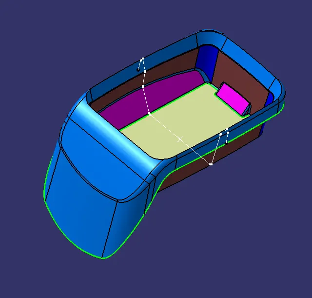
creating an inspecting line on both sides of the intersection.
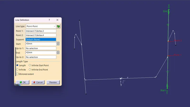
performing the same process on other side of the class A surface. then after crate a bisecting line
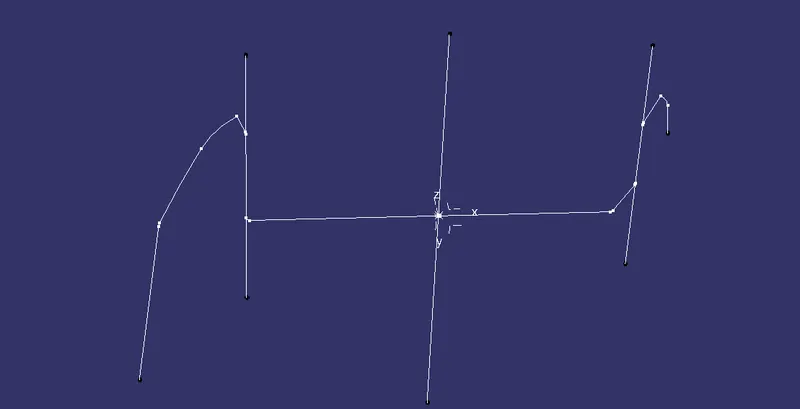
This bisected line is the tooling axis
now we are gonna perform the draft analysis for the Class A surface
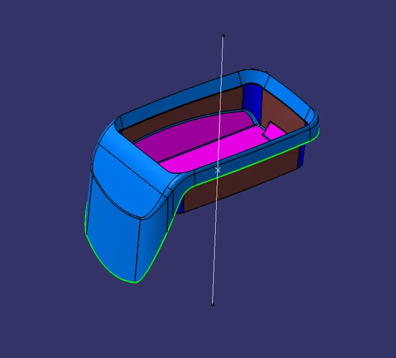
navigate draft analysis
dreg the compass and place over the tooling axis
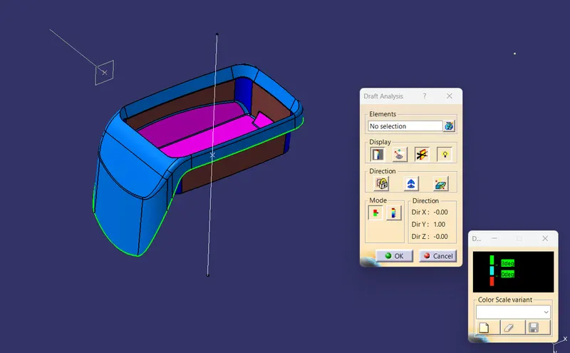
set the drat 3 deg. select the class A surface ( click anywhere)
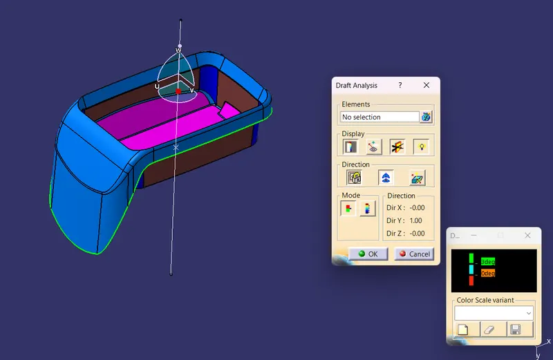
we can start the work on Class B and Class C surface and later we create close surface and create a solid part
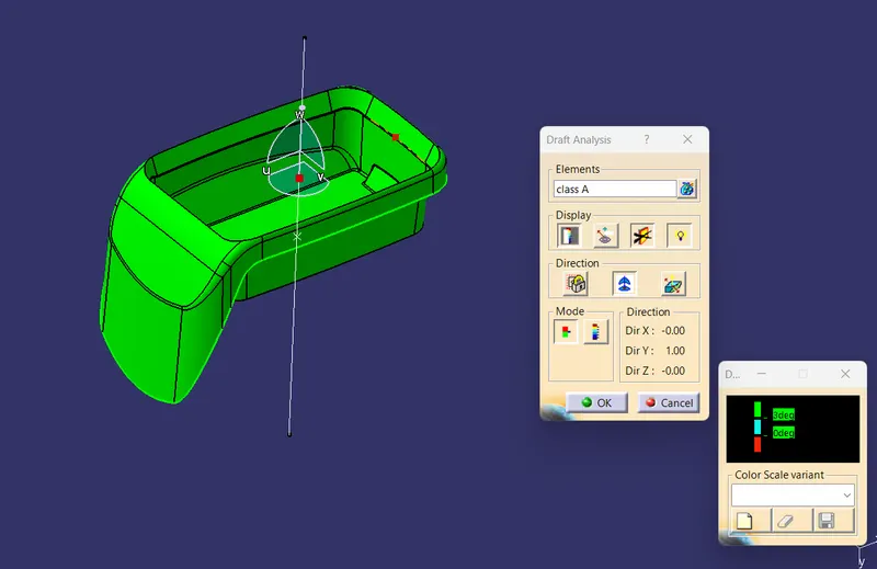
draft analysis of the complete coin holder (check whether the part is manufacturable or not)
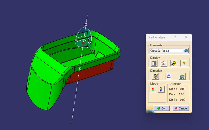

Part can be manufactured
creation of close surface
Base
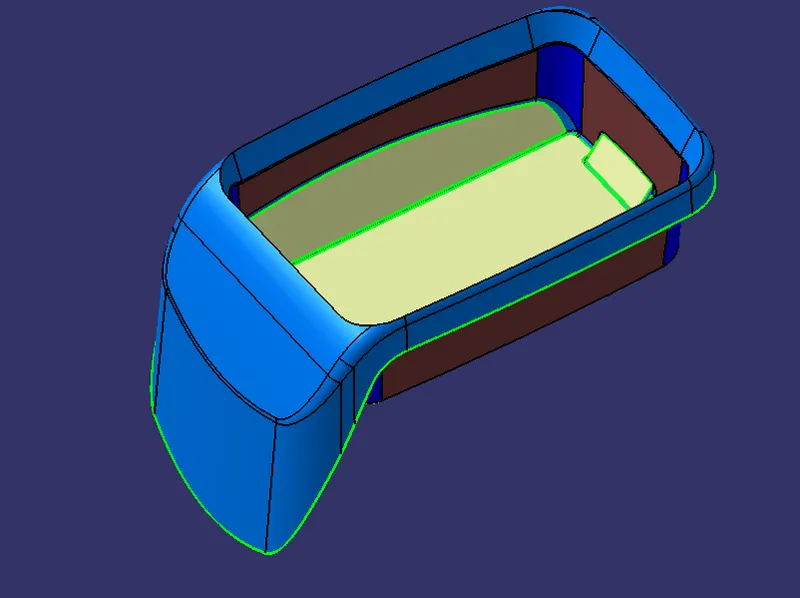
extract
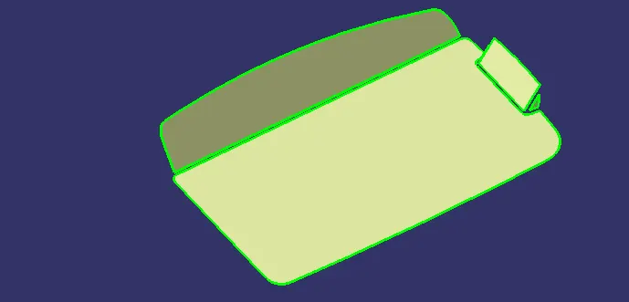
untrim
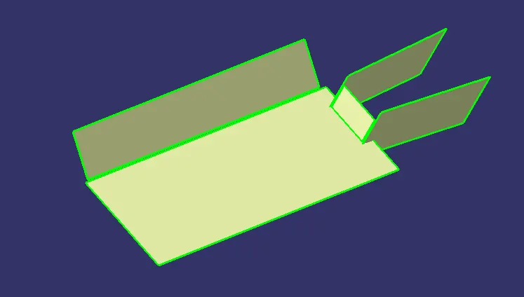
extrapolate
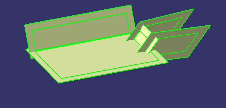
trim
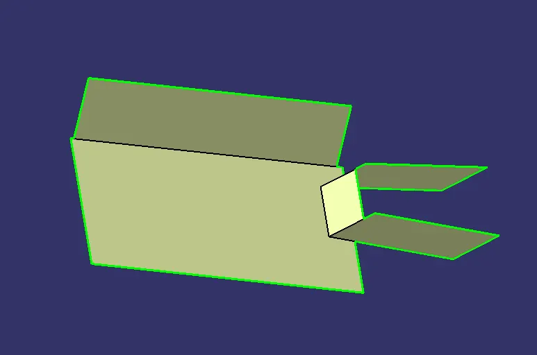
offset 2.5mm
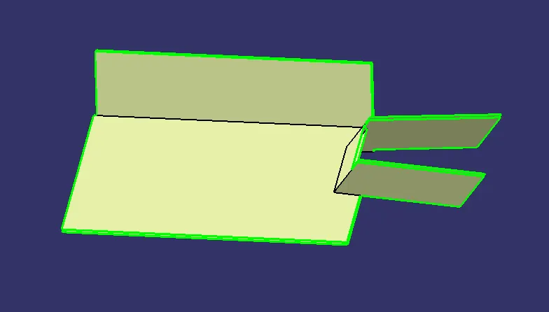
side wall
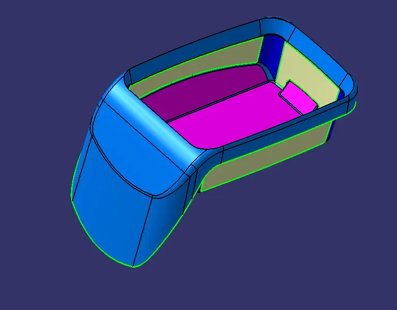
extract
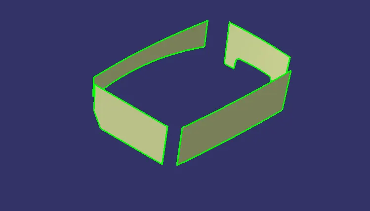
untrim
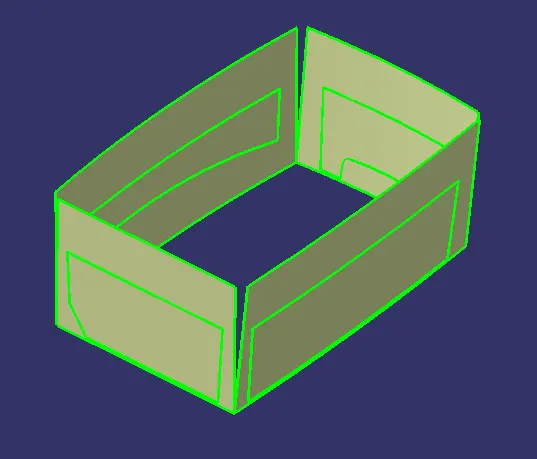
extrapolate
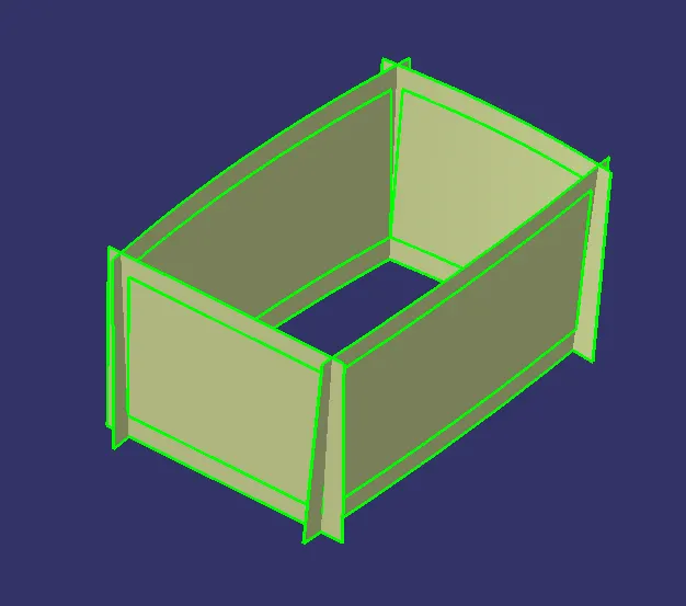
trim
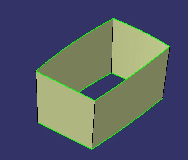
offset 2.5 mm
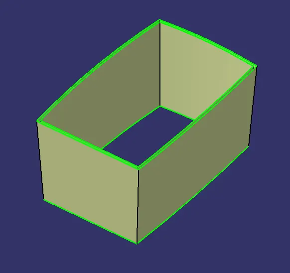
upper wall (inside)
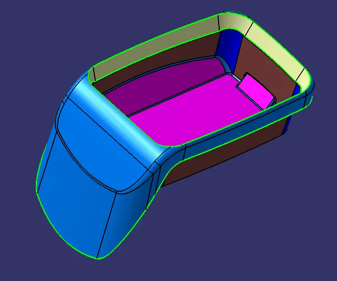
multiple extracts
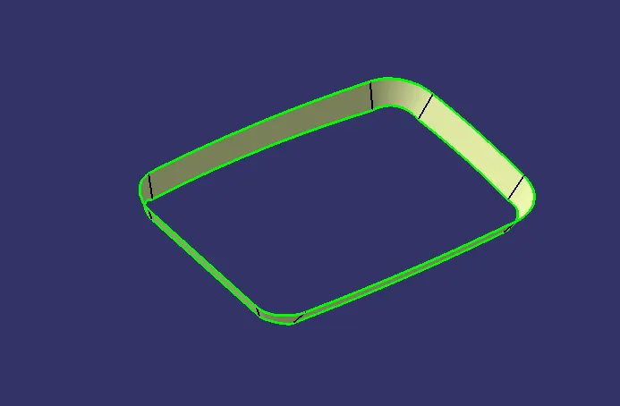
extrapolated
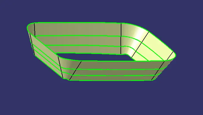
offset
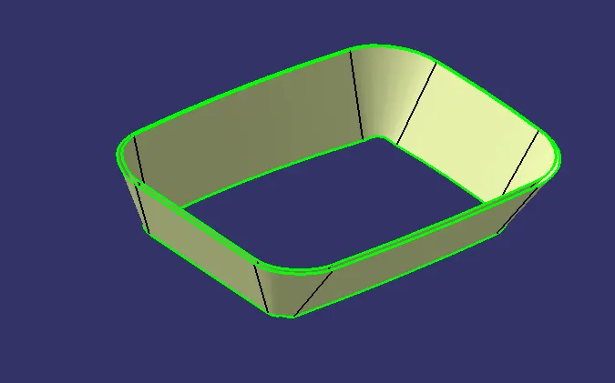
outer wall
extract
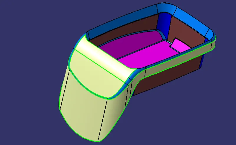
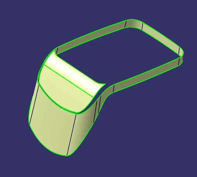
untrim
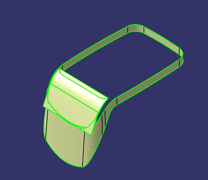
offset
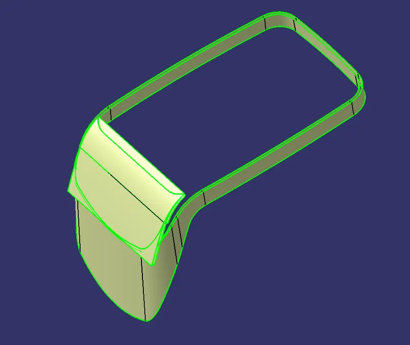
edge extrude
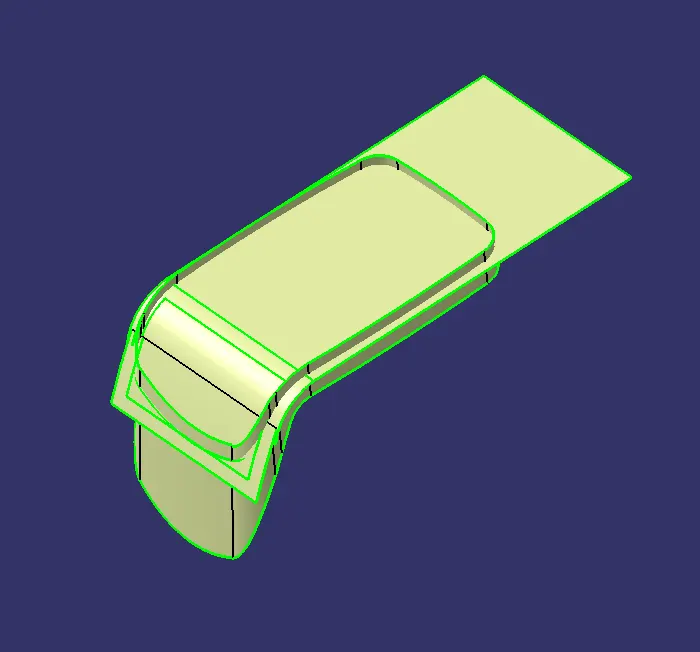
trim
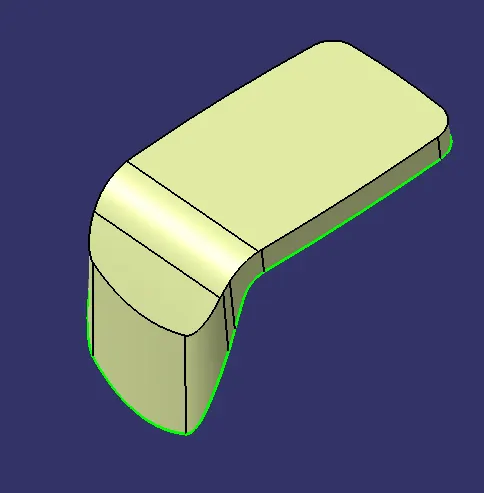
trimming of class B
base + side wall + upper wall + outer wall + top wall
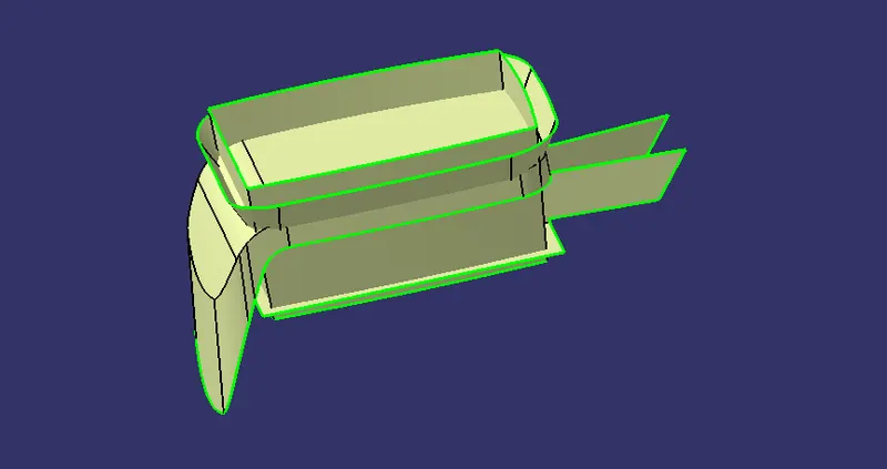
base + side
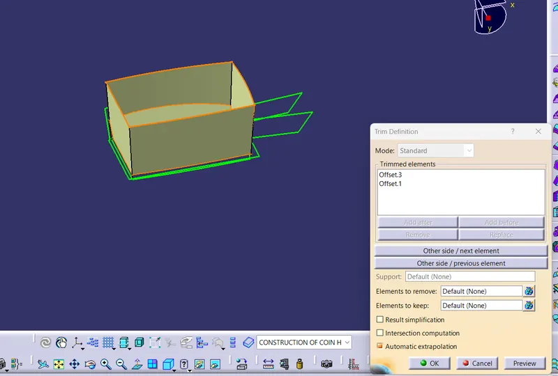
upper + trimmed base
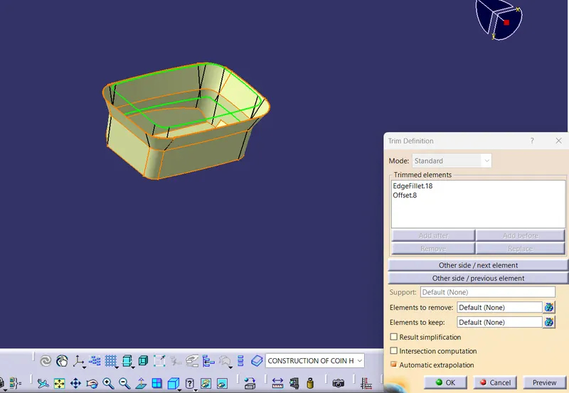
outer wall
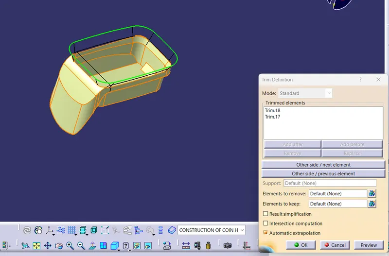
top wall
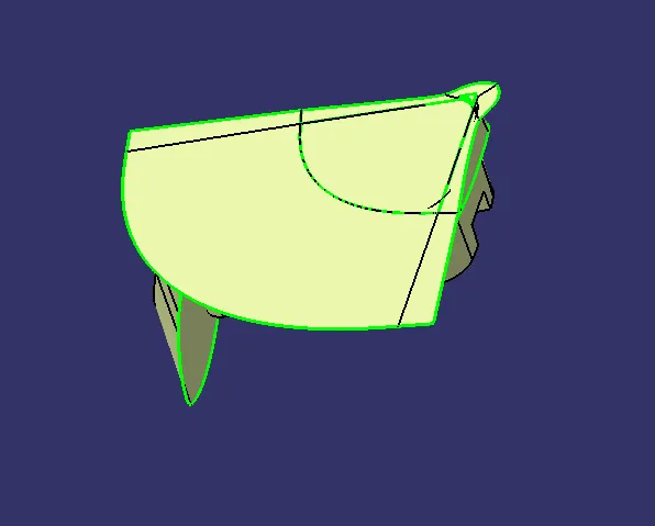
complete B surface
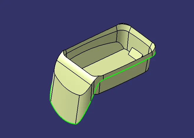
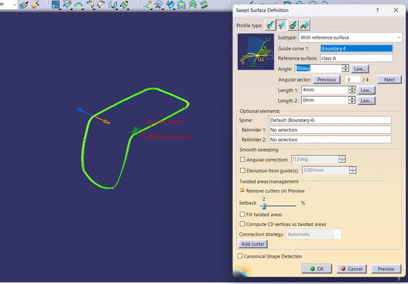
Class C surface creation
boundary command
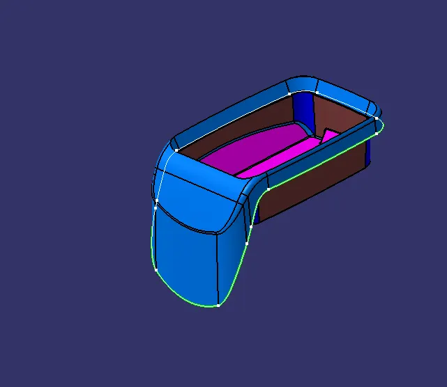
sweep with the reference surface
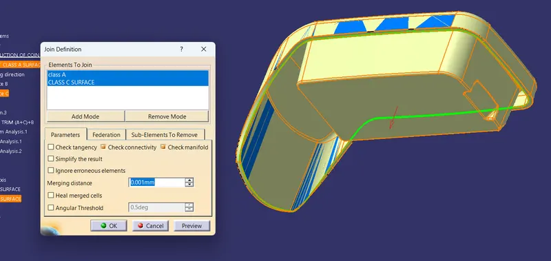
Join A+C
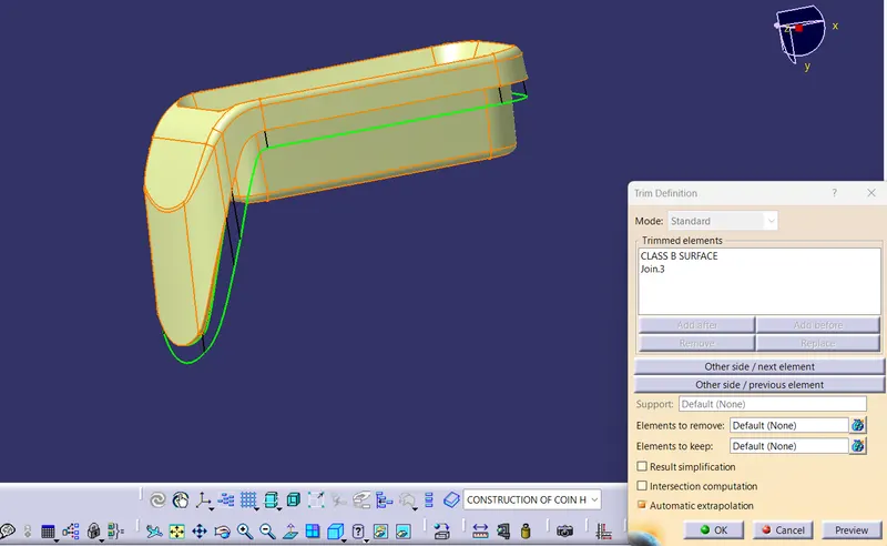
trim with class B surfce
A+B+C surface (close surface)
with given fillet
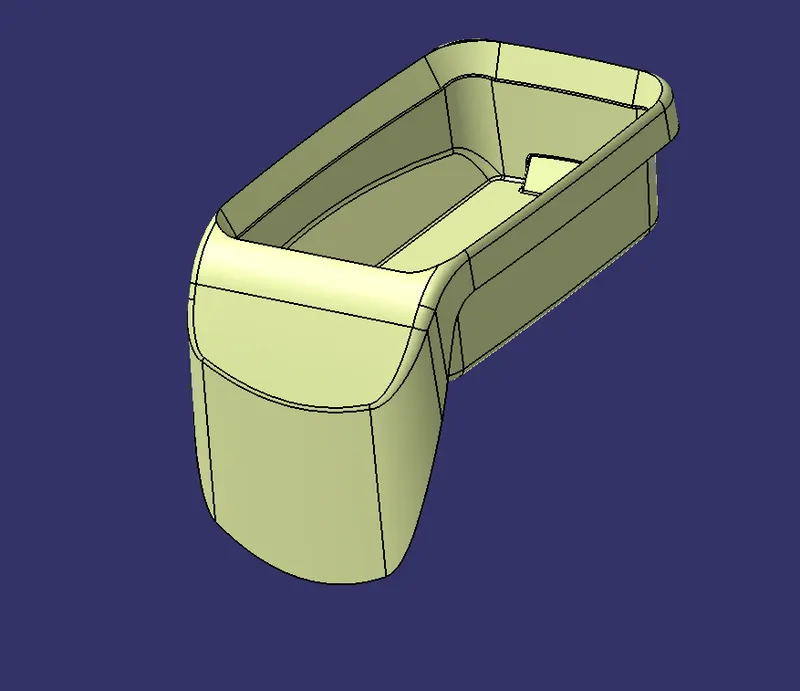
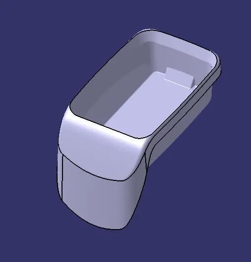
isometric view
front
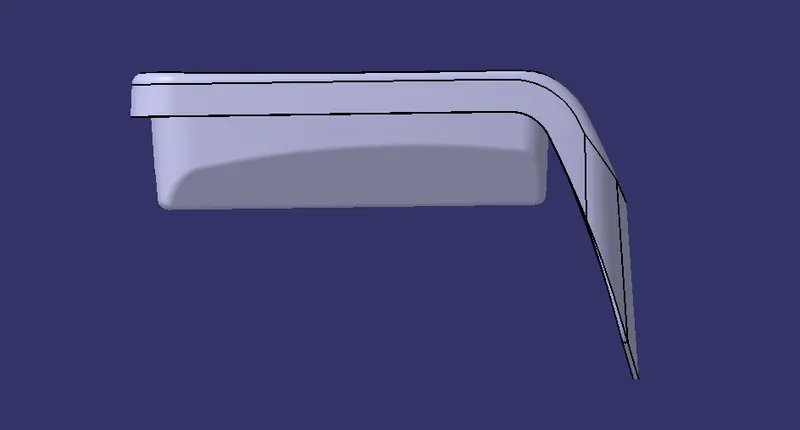
side
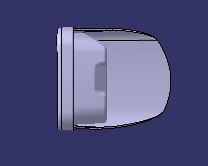
top