Week 8 - Challenge 4 - Bumper
Report on tooling axis creation and draft analysis
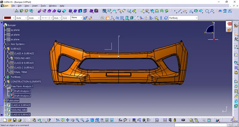
The given class A surface of the bumper is in a U shape when viewed along Z axis.Hence the tooling axis cannot be in the X and Y axis domain.Tooling axis must be directed around Z axis only.
Tooling axis creation
1.insert a point on the surface of the bumper at the midpoint.
2.insert an axis system projected onto the point.
3.visually analysing for various surfaces which are at an angle parallel to the assumed tooling axis.
4.As the surface is split into symmetrical two halves,The tooling axis must be perpendicular to the surface that is along Z axis.
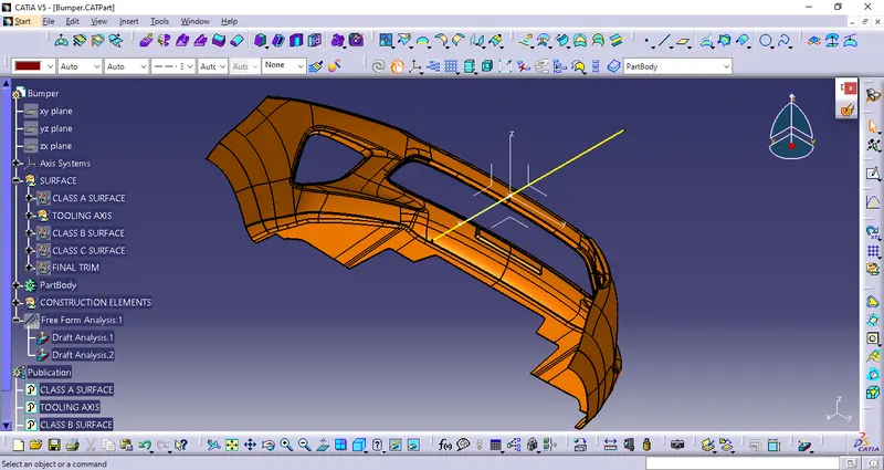
5.according to the bisecting method lines are drawn on The surfaces which are parallel to the tooling axis and a bisecting line is projected from those two lines which becomes the tooling axis.
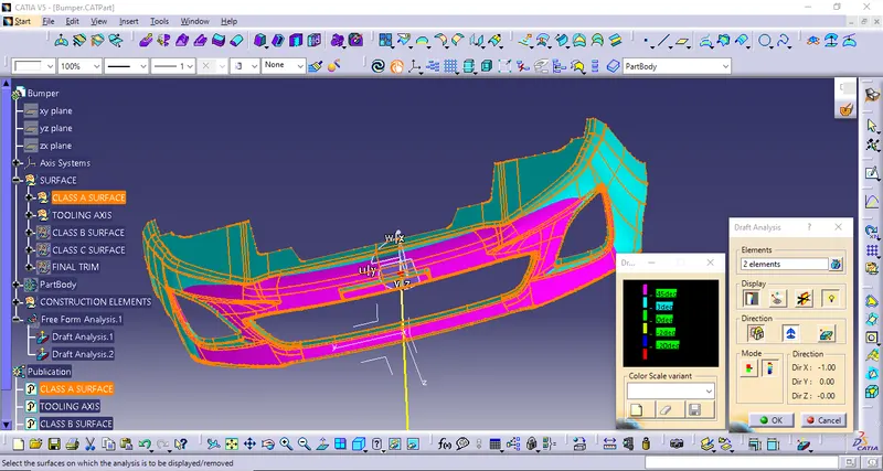
6.on the draft analysis command,The class A surface is chosen and the axis system is aligned with the tooling axis and locked, display is chosen and the mode of display showing colour schematics is chosen.
0°-3° choose as green.
3°-45° chosen as blue.
3°-45° chosen as blue.
Above 45° chosen as pink.
7.various angle requirements and their colour codes are entered and analysed for the draft of the surface.
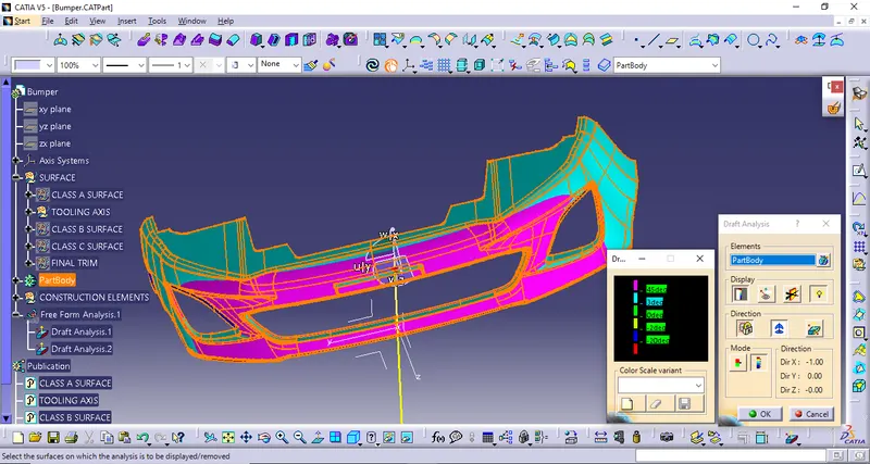
draft analysis is performed even on the part body and after performing the feature draft analysis the part body was found to be meeting the requirements of the draft.
Excuse me,I have taken thickness of component to be 2.5mm mistakenly.