Week 8 - Challenge 4 - Bumper
AIM
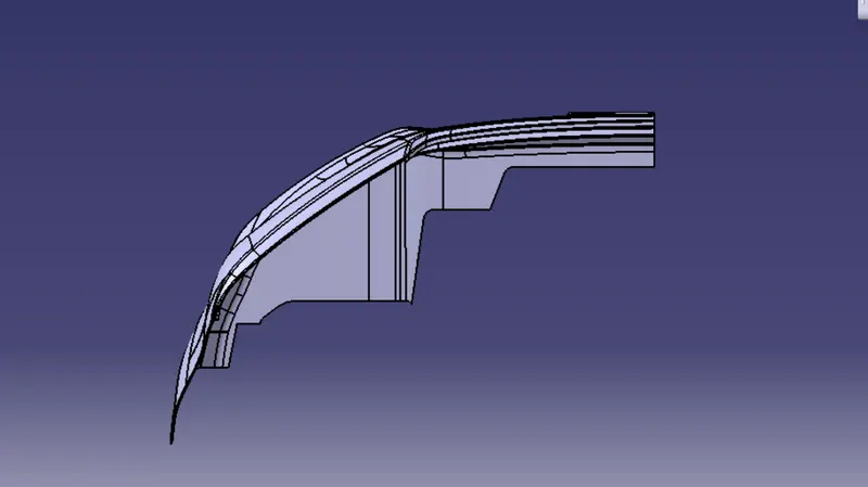
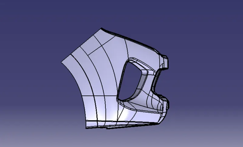
To make a model from the provided class-A surface.
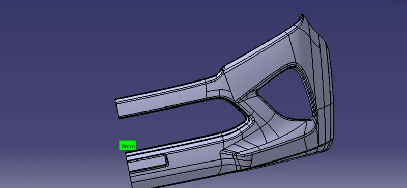
CLASS A SURFACE:
The given class A surface
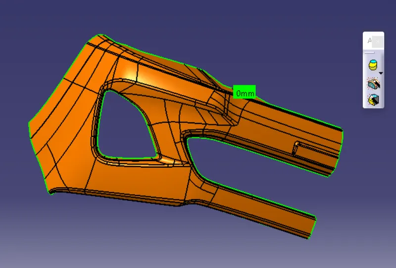
At first, take the base surface and create a center point on the surface and insert the axis system.
BISECTING METHOD
This method is used for the generation of the tooling axis for that purpose first we need to decide the direction of molding and then we create one dummy tooling axis for the reference to the purpose.
In this method, we select the surfaces which can create problems and take intersections in the x and y-direction. By using these curves we draw two lines and then draw a bisecting line from these two lines in the x-direction and y-direction.
If it is done in x-direction then it is called a tooling axis clearing x-direction and if in y then tooling axis clearing y-direction.
After completing this we need to draw a final line bisecting this two tooling axis in the X and Y directions to
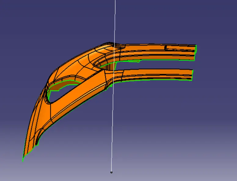
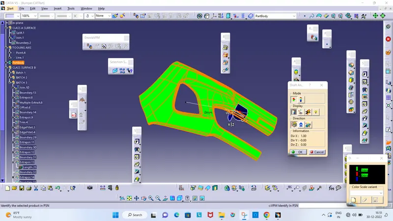
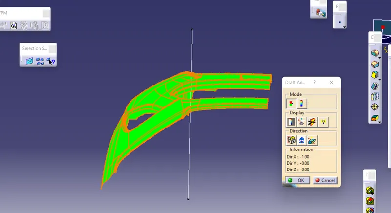
The next step is to perform the draft analysis to check the tooling axis and understand the surface of the given class A.
Select the insert option from the menu bar and find the analysis tool,
In analysis, there is a tool named Featured Draft Analysis select.
The next step is to move the compass on the tooling axis.
Then in the color graph give the maximum and minimum draft angle and lock the compass then select any surface to show the result.
the result will be color differentiated as green, red, and blue .then give ok to save the result.
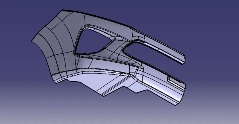
CLASS B SURFACE
First take the A surface take the 3 mm 3 batch filled error,solve the 3 batch error
BATCH 1 F
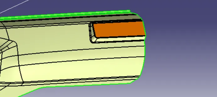
BATCH 2
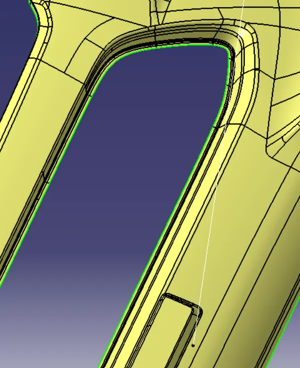
BATCH 3
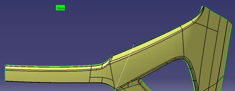
CLASS C SURFACES
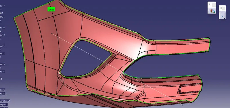
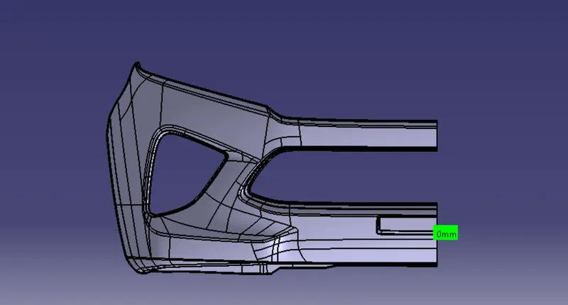
FOR FINAL MODEL
Join class A and class C surfaces together.
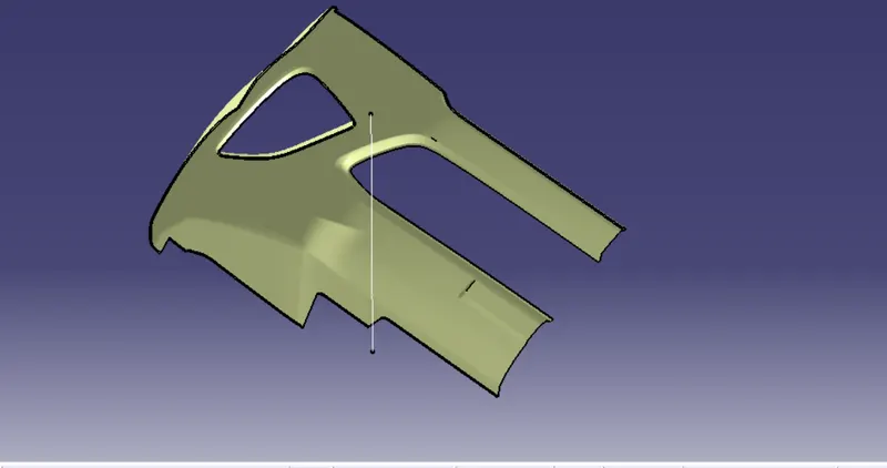
Go to the part design and close the feature.