Week 8 - Challenge 4 - Bumper
1) ISO
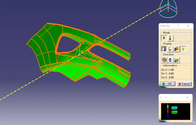
2) FRONT
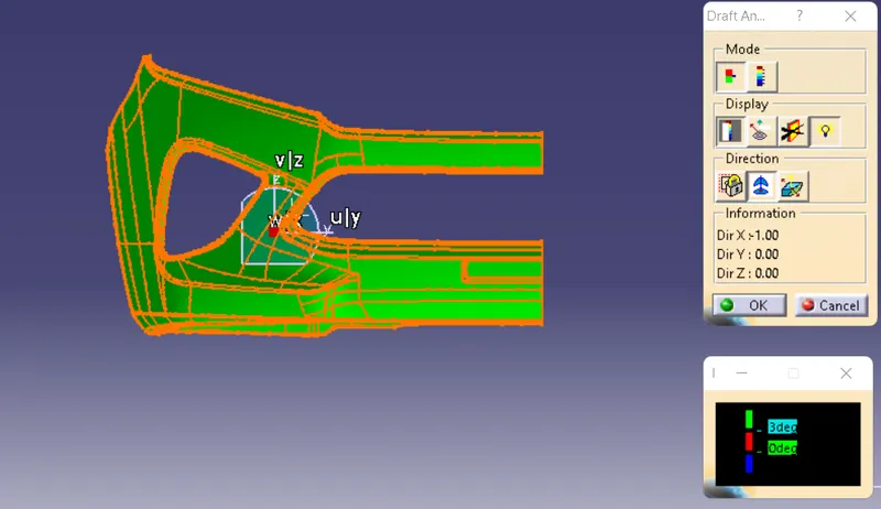
3) SIDE
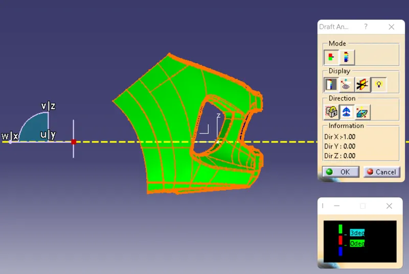
4)TOP
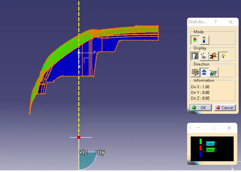
5) DRAFT ANALYSIS CLASS A
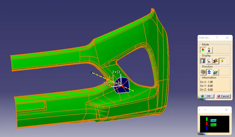
6) DRAFT ANALYSIS FINAL COMPONENT
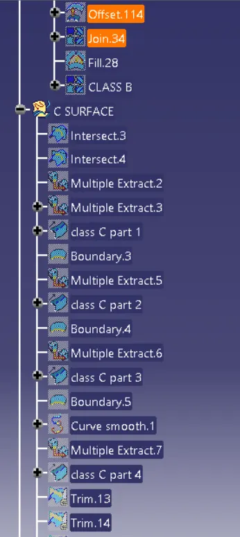
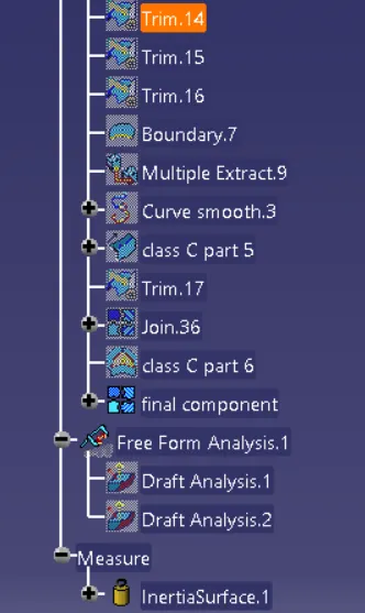
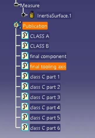
7) FEATURE TREE
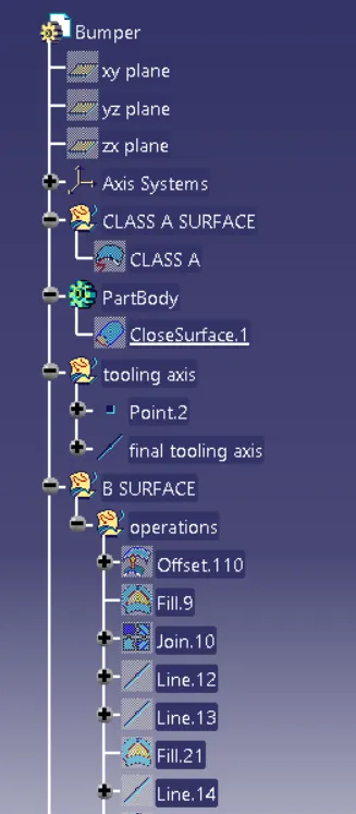
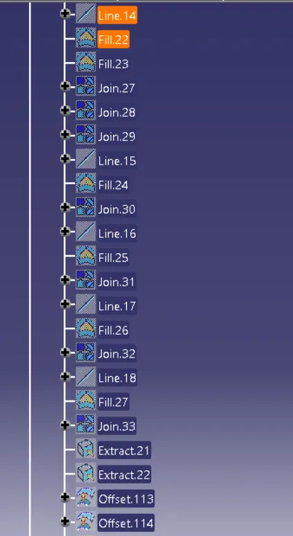
REPORT
- A detailed report should be done explaining the draft analysis and the tooling axis creation.
What is a draft analysis?
No parts can be ejected from the tool if it is having a straight 90 degree profile from its base surface. A small draft angle is provided to each and every area of the component in order to get an easy removal of the component from the tool. Draft analysis technique is used to analyze whether our part model created in cad is manufacturable based on the draft condition applied. Here the part should get easily removed from the panel dies (in case of Sheet metal part) or Mold (in case of plastic). Here we are providing a direction in which components should eject inorder to get an easy removal of components from the tool. In other words it also lets us know whether the model is having a draft angle and how much is the draft angle from the tool direction.
The Draft Analysis command enables you to detect if the part you drafted will be easily removed. This type of analysis is performed based on color ranges identifying zones on the analyzed element where the deviation from the draft direction at any point, corresponds to specified values.
On what type of components we perform Draft Analysis?
Draft analysis is performed on the components where the ejection of materials happens after the material is made inside the tools in case of Automotive Sheet Metal manufacturing, the blank sheet after turning into automotive panels like Hood, Fender, Roof, Side Doors, Back Doors etc. need to be removed from Panel Dies. If a considerable amount of draft angle is not provided, the removal components from the tool will be difficult. Same in the case of mold(plastic component) after getting filled inside the core and cavity, it needs to get ejected easily with the help of ejectors.
What factors should be considered while doing the draft analysis for Plastic/Automotive Sheet Metal parts?
The major consideration of Draft Analysis is whether sufficient Draft Angle is provided on the component Components while designing should be provided with a considerable amount of draft angle depending on the manufacturing consideration. For Plastic components wo provide a dratt angle of 3degree(Draft angle of 0.5 is given ideally to the features inside the plastic part). But for Automotive Sheet Meta Parts, it will be from 7 degrees or more.
STEP 1
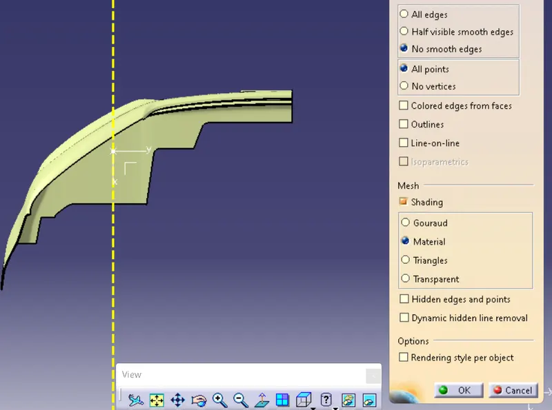
Change the view mode to Customize View Parameters and select Material option from the Mesh
STEP 2
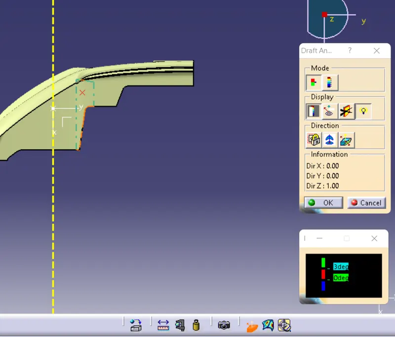
create a dummy tooling axis by first creating a point and then a line to one of the plane axis
STEP 3
Draft Analysis option are available inside following workbenches:
• Part Design
• Generative Shape Design
• Wireframe and Surface for Building
• FreeStyle Shaper
open draft analysis and click on compass and drag it on the axis
STEP 4
click any where on the part
the appearence of component will change
Try zoom in and check if each and every region of the panel is showing green, it in some region, red or blue is showing instead of green, those negative regions are below 7 degree and have no draft applied on those regions.
those blue and red negative regions needs to be changed.
- An explanation should be given on the way of creating the tooling axis, particularly the Bisecting method.
What is tooling axis?
Tooling axis: The direction in which the mold or core and cavity opens is the tooling axis.
step 1
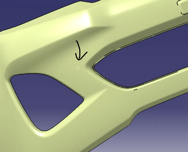
create a point using curve option from point tool on the surface
step 2
using that point create a line to draft direction that line will be called dummy tool axis
step 3
then create a plane that can cuts the surface into two and get a sketch of surace crossection
step 4
using the sketch lines try to create two lines that will intersect along with the dummy tooling axis
step 5
the line which is created is the tooling axis and this is called bisecting method.
here i used a different method to find the tooling axis ,
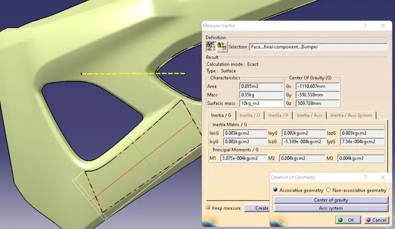
first i found the point by center of gravity and then by using that point,
i made an axis by until i got the satisfied draft analysis.