report on design , assembly of Yacht with rendering in solid works photoshop360 and visualize
1.Radar mast feature tree
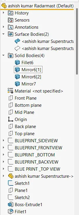
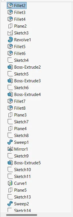
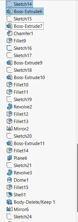
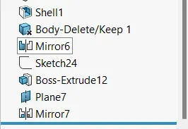
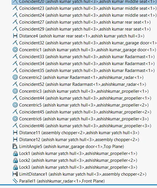
2. yacht assemmbly feature tree
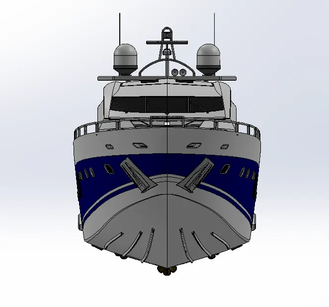
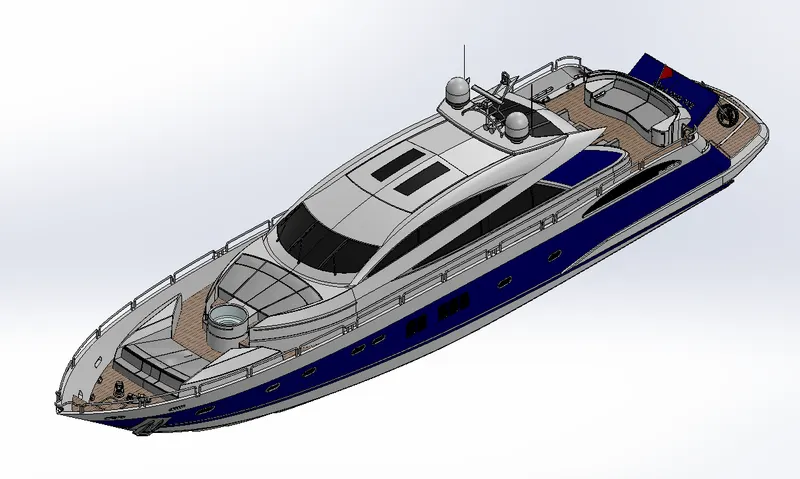
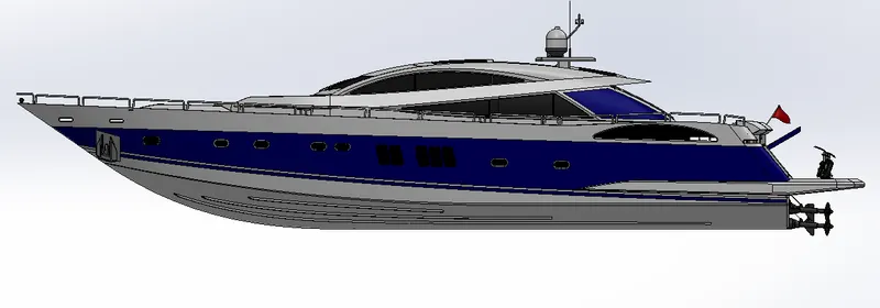
3. Report on yacht Design, assembly and rendering
Design, Assembly, and Photo_Realistic Rendering of an Yacht
OBJECTIVE
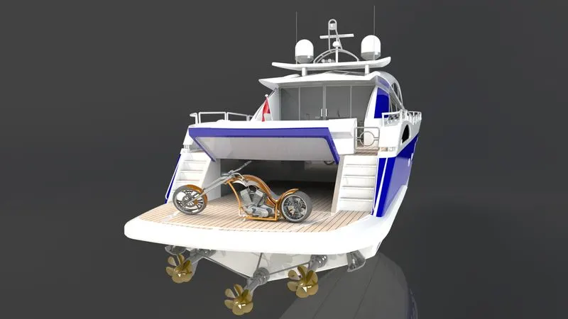
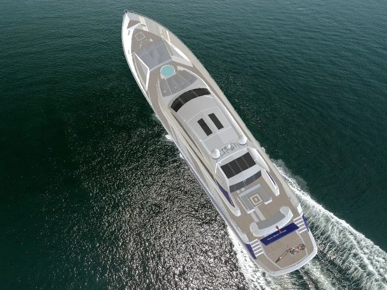
The objective of the project is to design and model all the parts of an American Predator Yacht and assembling it to create the Photo-Realistic rendering of the yacht.
INTRODUCTION
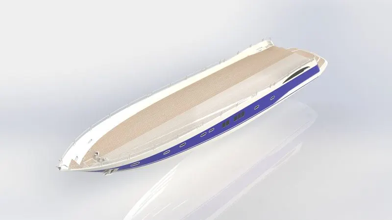
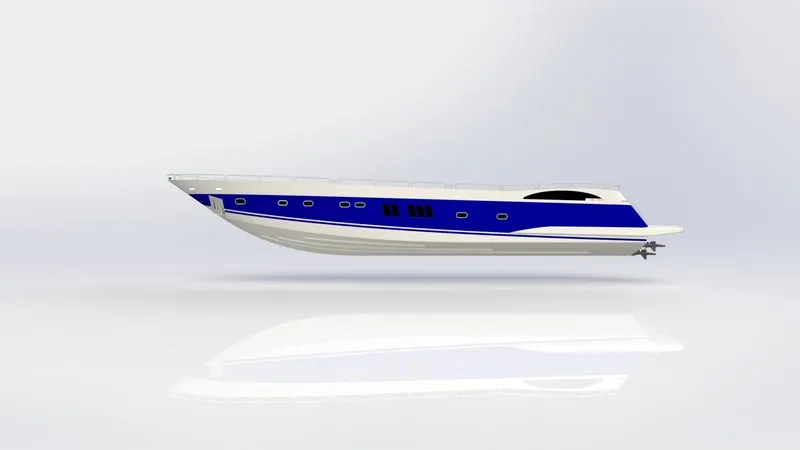
Computer-Aided Design or CAD practices are extensively popular in various contemporary professional domains including Product Design, Industrial Design, Engineering R&D, etc, and thus counts as an essential pre-requisite for the role of a Design Engineer. The purpose of this CAD project is to obtain hands-on experience and insights on different aspects of 3D modeling such as solid modeling, surface modeling, assembly creation, as well as to photorealistic rendering practices. The model created in this project is a cosmetic version of the Predator Super Yacht ie the emphasis is primarily on the outer body (also called as the A-Surface) and the aesthetic features (with customized appearances), and not on the internal technical functionalities. The whole model is divided into components that are created individually and assembled together by defining the constraints, resulting in the final desired product.
Model Components:
- Propeller
- Radar (Scanner)
- Hull
- Garage Door
- Seats - Front, Middle, Rear
- Superstructure
- Radar Mast
Besides the components, a file containing the blueprints (referred to as Blueprint Setup) of the Yacht model in various views is also created as reference for the body contours. Each view is inserted on to appropriately placed sketch planes, named as Front, Back, Bottom, Top and Mid-Plane, which provide an image reference to work out the projected curves and surface trims.
3D MODELING TECHNIQUES
1. Solid Modeling-The method involves manipulating the bulk of on object via volume addition or subtraction commands. The object is treated as watertight as the internal details are also included in the model. Boolean operations like union, intersection and subtraction can be applied on solid bodies to form the required geometry. Intricate detailing can be carried out in solid modeling much easily and also since the geometry can be made parametric, revising the steps updates the whole model accordingly.
2. Surface Modeling - This modeling focuses more on the outer shell of the object ie, the exterior tangible surface. Defining the boundaries and shaping the surfaces through complex curves form the essence of this type of modeling. It allows free-forming of shapes much flexibly that aid in creating aesthetically appealing product designs.
The objec formed using surface modeling is a hollow entity and is not considered watertight by default. However, if a closed volume with multiple surfaces is formed, these can be joined together with appropriate spatial or gap tolerance and then converted into a solid body.
Commands Used in the Model:
General - Sketch, 3D sketch, Insert [Part], Trim/ Extend Entities, Offset Entities, Convert Entities, Project Curve, Reference Geometry [Plane], Helix and Spiral, Split-Line, Split, Mirror, Linear Pattern, Circular Pattern, Sketch Pattern, Sketch Picture.
Solid Model-Boss-Extrude, Boss-Extrude [Thin], Swept-Boss, Revolved-Boss, Lofted-Boss Cut-Extrude, Dome,
Shell, Fillet, Chamfer.
Surface Model - Extruded-Surface, Offset-Surface, Swept-Surface, Lofted-Surface, Filled-Surface, Boundary Surface, Ruled-Surface, Extend-Surface, Trim Surface, Knit Surface, Thicken, Delete Face, Fillet.
DESIGN METHODOLOGY
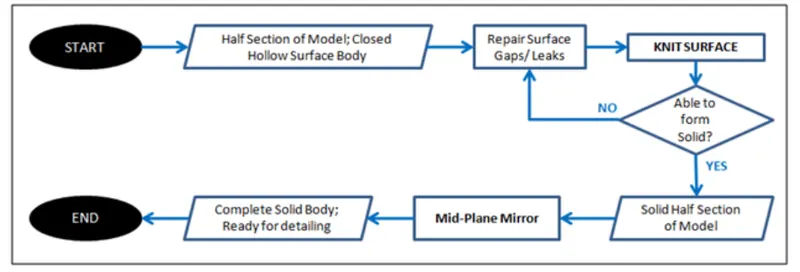
Most of the transport vehicles have design geometry symmetric about their vertical centre plane i.e. Mid-Plane, or in other words, the two half sections of the object are mirror image of one another. The same approach is taken while making the Predator Super Yacht CAD model. Only one half of the components are created which show symmetry about their mid-planes, and the other half is generated using the 'Mid-Plane Mirror' method to obtain the complete component model.
On the other hand, the components namely Radar (Scanner), Garage Door and Radar Mast, are built directly as solid bodies and completed using the Mid-Plane Mirror method.
MODELING THE COMPONENTS OF THE SUPER-YACHT
(1) Propeller
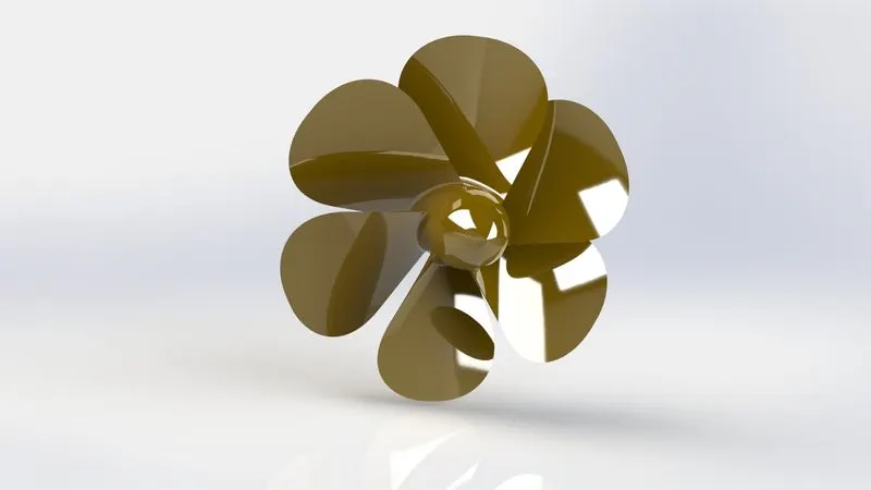
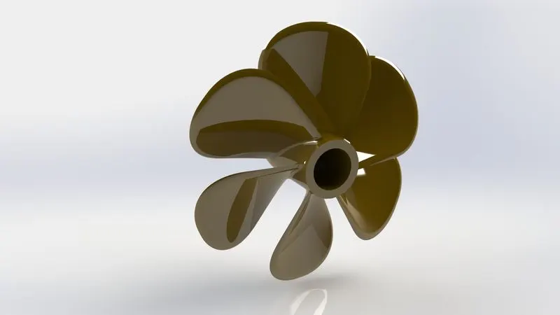
The section sketch of the propeller hub is revolved as a solid and bore for the shaft created. The cross-section of blades is sketched on two distant parallel planes for lofted-boss feature (with apt twist). The curve to the blades is given by filleting feature, and is patterned around the hub using circular pattern
.
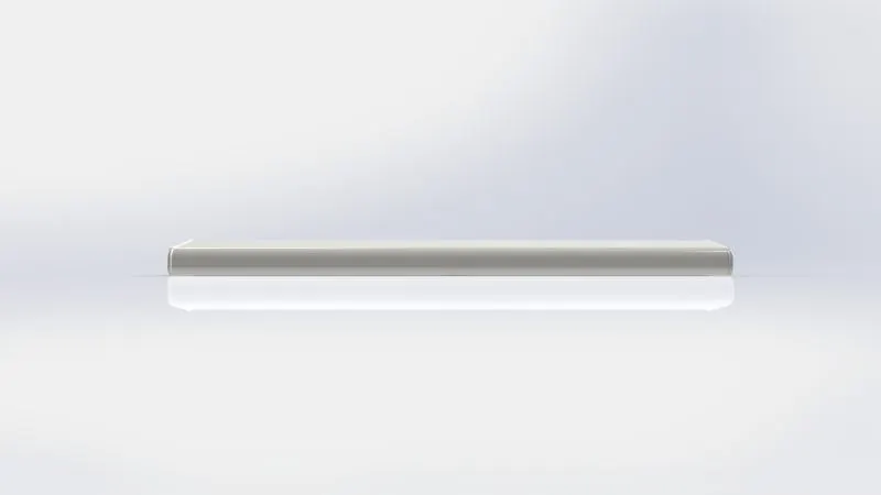
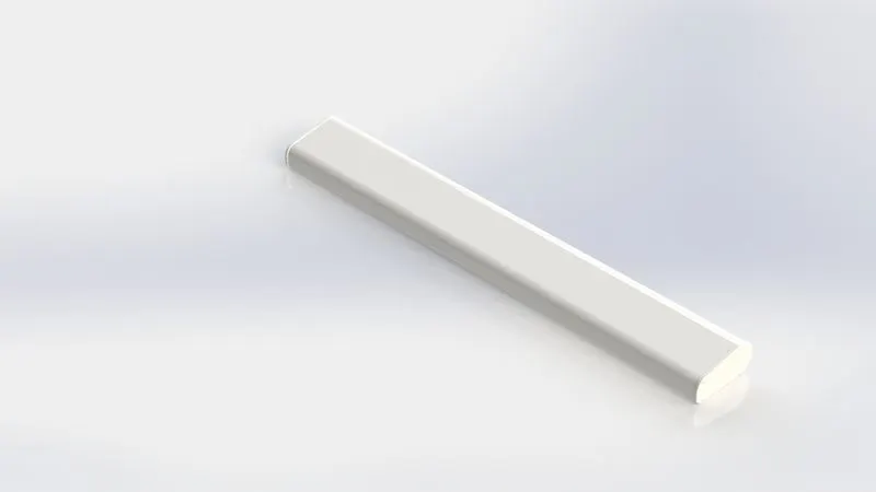
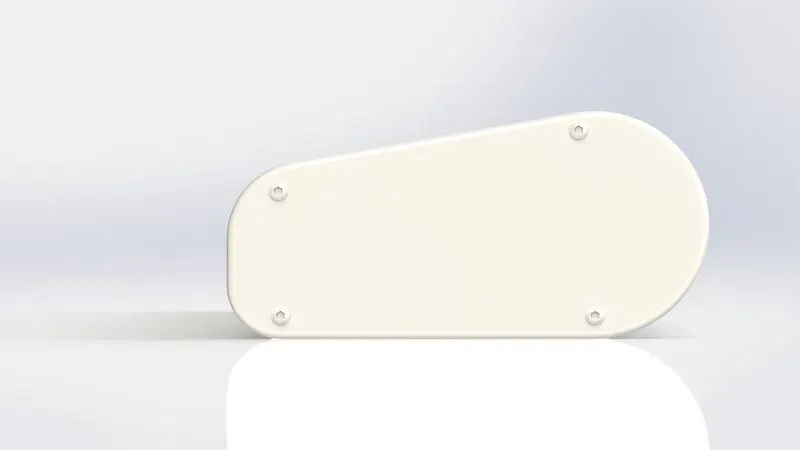
(ii) Radar (Scanner)
One half of the radar is built by extruding the base cross-section and offset entities consecutively as solid entities. Fastener heads are made then copied to other points using sketch pattern. The complete model is created using Mid-Plane Mirror method.
(III) Hull
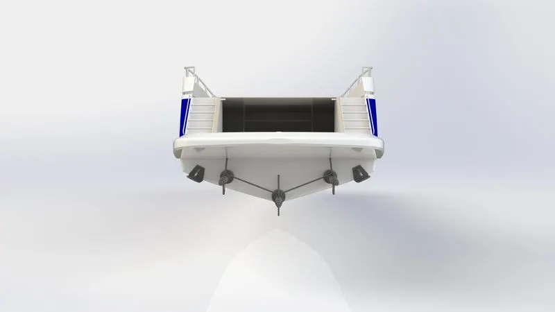
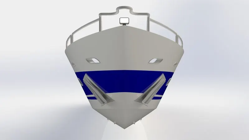
With the help of the Yacht Blueprint setup, the outer contour of the hull is generated using projected curves and multiple surfaces that are later knitted to form a solid, upon which the further desigh detailing is based such as the propeller shafts, anchor hinges, railings, staircase and the garage region (whose split body volume is exported as a separate part for garage door model). A coincident surface to the deck is stored as a separate surface body to be used as base reference for the seats. Desired decals and appearances are added after creating the entire hull via Mid-Plane Mirroring.
(IV) Garage Door
The solid form for the tilt-up canopy type garage door is obtained from the region volume spilt from the hull. By removing excess volume and using shell command, the shape of the door is obtained. Since the split volume was obtained half model of the hull, Mid-Plane Mirroring yields the full door. Suitable engraving and appearance setting adds to the final looks.(V) Seats
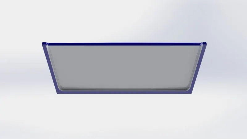
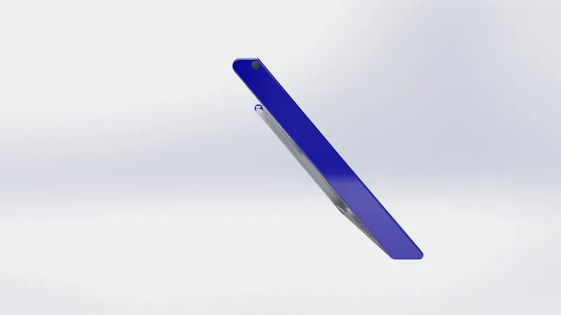
As a reference to start modeling the seats, the copy of the deck surface alone is inserted in within the Blueprint setup file. The surface serves as the plane to create necessary 2D sketches. The seat modeling uses the Mid-Plane Mirror approach as well. Further, to make separated solid volumes for entities like Jacuzzi mattress, cushions backrest, etc, the Offset-Surface and Cut-Extrude commands aid in giving spatial gaps that split one solid body into multiple meaningful sections, which can later be mirrored individually.
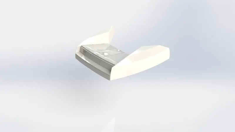
• Front Seat
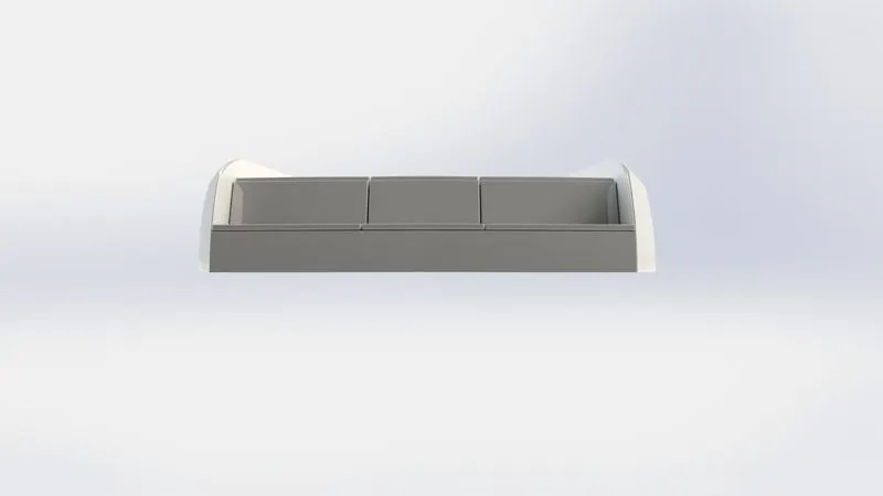
The molded contour of front seat side structure is built initially as a closed surface model. The Jacuzzi mattress and seats are made as revolved entities to obtain the curved orientation, which are separated from the base structure.
.
Middle Seat
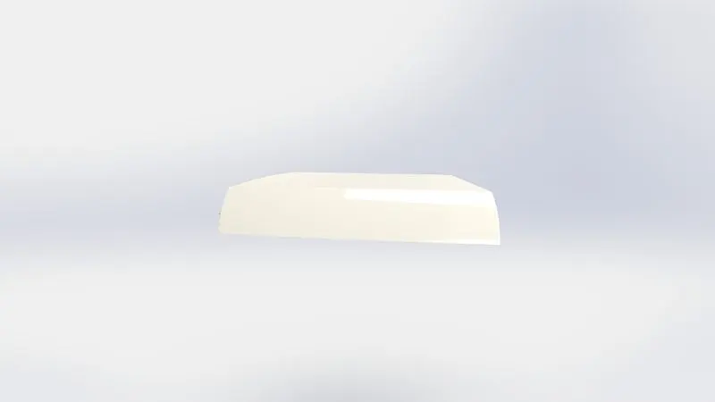
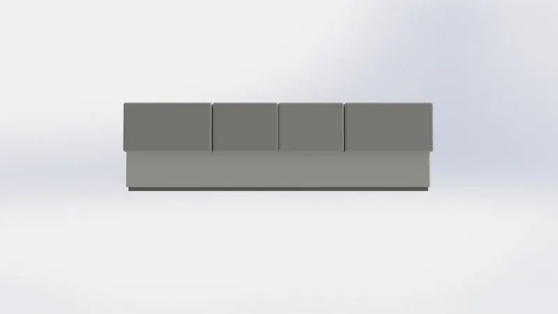
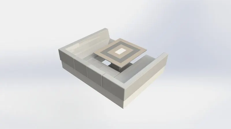
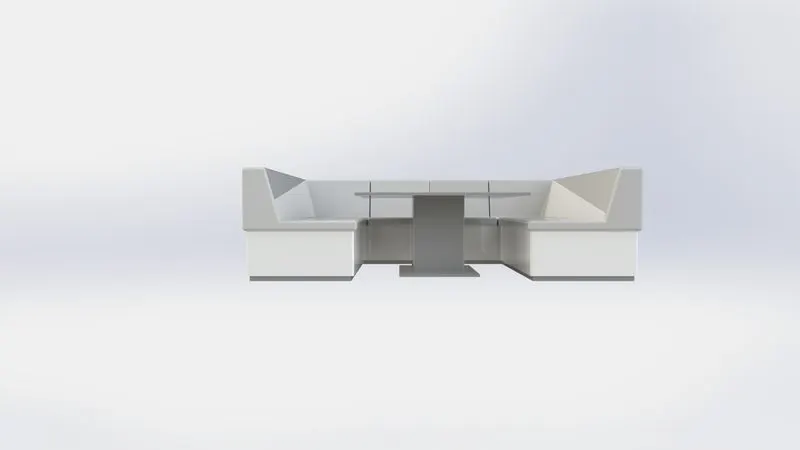
The middle seat is simply created with the basic solid modeling commands. Reference planes with required spacing are used to separate different elements like base, cushion and backrest. The centre-table is however, made as a whole entity without requiring to be mirrored.
Rear Seat
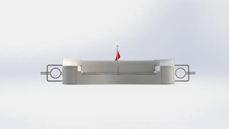
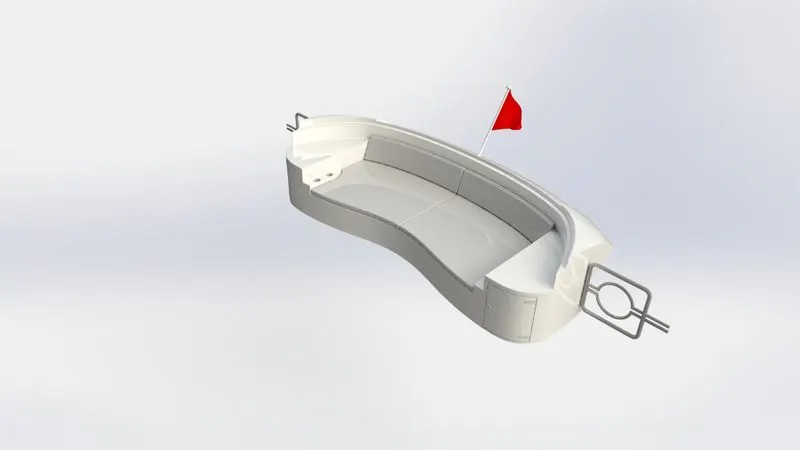
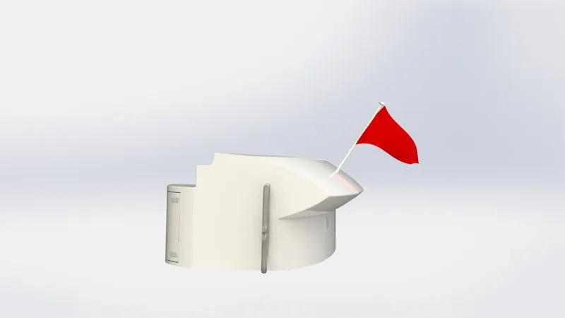
The outer shell of the rear seat is formed via combining several surfaces together. Instead of creating redundant reference places to incorporate details (like boundary gap for side-drawer, the hinges and knob, etc.), the sketches for these purposes can be drawn in a single plane consecutively and transferred on to the a desired surface using the 'Offset from Surface' property of these commands. The side grilles are generated as separate solid entities. After Mid-Plane Mirroring, the flag post is made and the flowing flag affect is achieved as a lofted surface through sets of 3D splines.
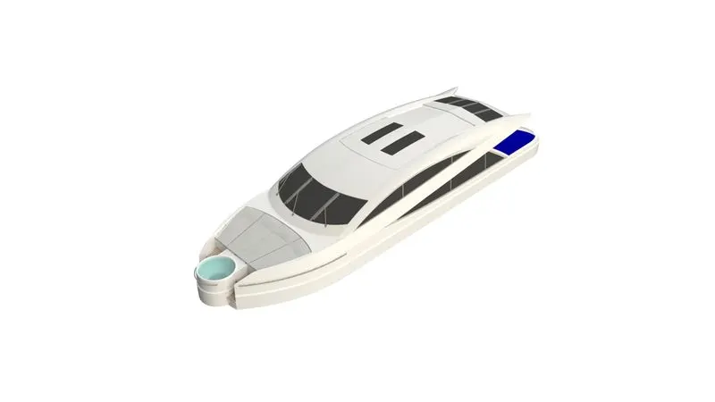
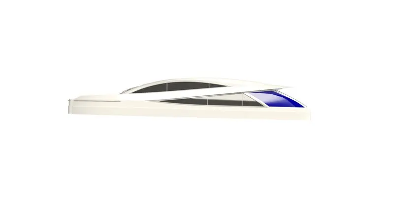
(VI) Superstructure
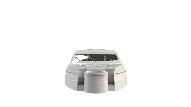
The Blueprint setup as well as the Deck surface (from the hull model) serves as the base reference to create the Superstructure. The complex A-surface (or the exterior shape) of the superstructure is formed by knitting together numerous surfaces, starting from the bottom side panels up till the rooftop.
As a fool-proof design methodology, knitting operation is performed after modeling every 3-4 surfaces. This helps to ensure that any occurring gaps can be diagnosed and corrected whilst modeling and thus, reduce the efforts for extensive revision of the model if any leaks come up. Again, 'Offset from Surface property is applied to transfer features to desired surfaces without having to create additional reference planes. A coincident surface copy of the roof panel where Radar Mast is to be attached, is stored separately (similar to deck surface) to be used as reference for modeling the same.
Different appearances are added to create effects for Jacuzzi water, windshield/ window glass.
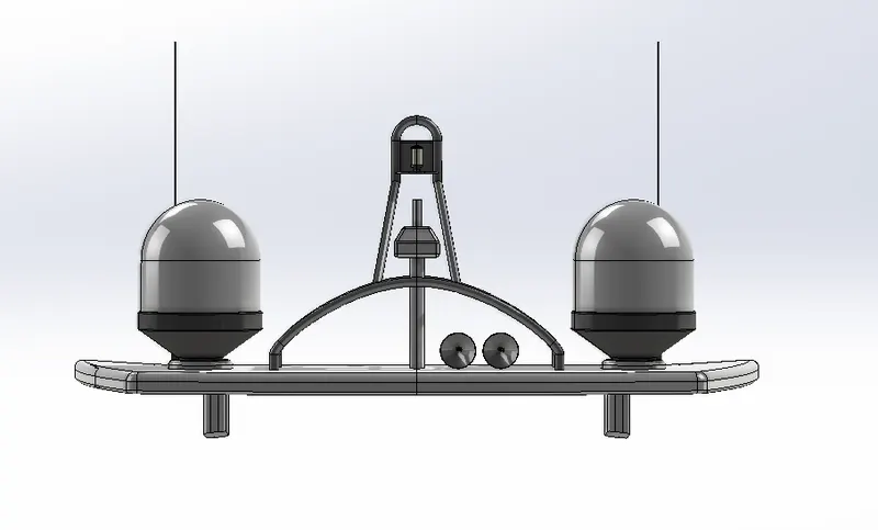
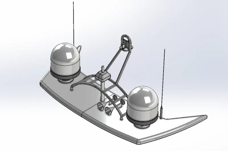
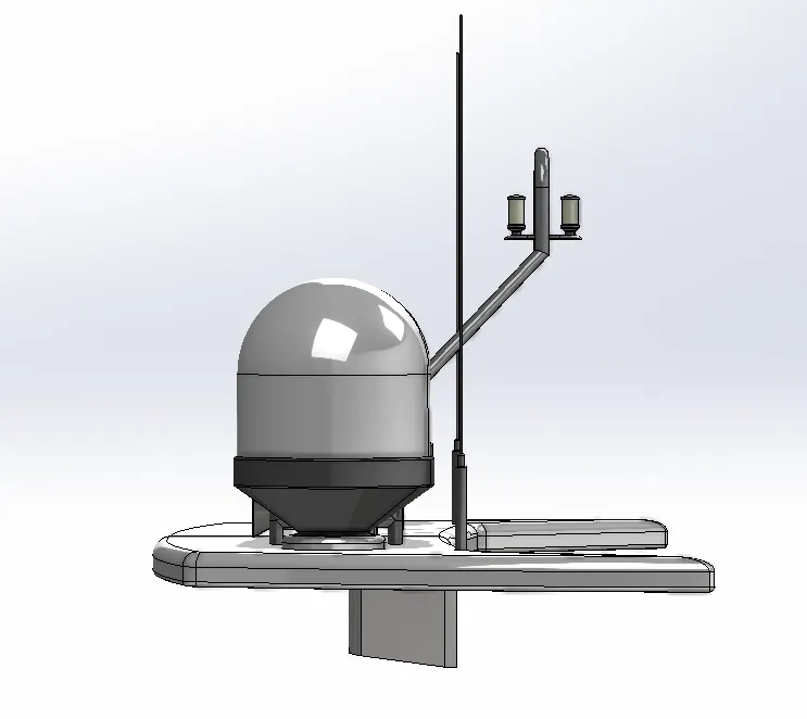
(VII) Radar Mast
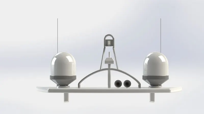
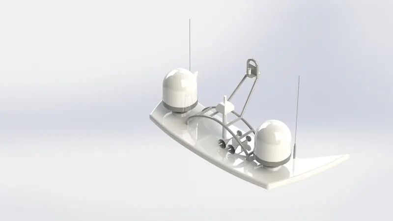
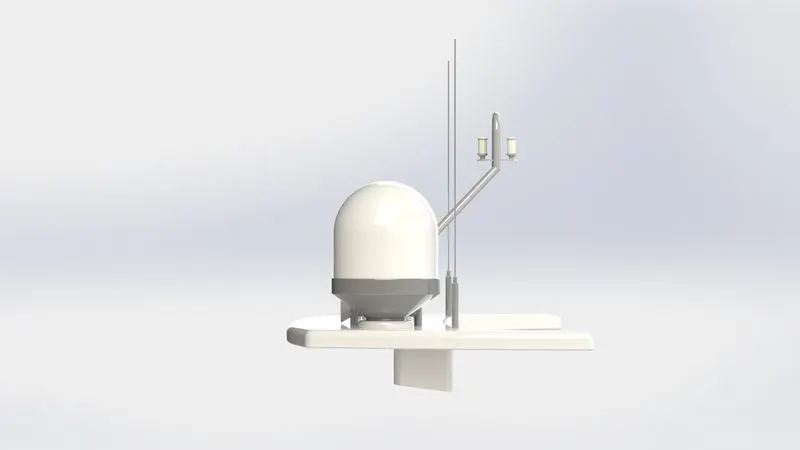
The copy of roof panel from the superstructure file serves as reference for this model. The winged base, transmitter housing, support railings, radio antenna, radar scanner mount, navigation lights, fog-horn are all created as solid bodies. The Radar Mast base mounting is extruded up to the roof panel surface for better integration during assembly.
Similar to previous Yacht components, Mid-Plane Mirroring yield the full model. However, since the fog-horns are not positioned symmetrically about the mid-plane, a separate reference plane is defined for mirroring the same and resulting in a set of fog-horns.
ASSEMBLY COMMANDS
• Smart Mate - A Smart mate is an assembly mating relation that is created automatically.
• Mate - A mate is a geometric relationship, such as coincident, perpendicular, tangent, and so on, between parts in an assembly.
• Mate group - A mate group is a collection of mates that are solved together. The order in which the mates
appear within the mate group does not matter.
• Sub-Assembly - A sub-assembly is an assembly document that is part of a larger assembly. For example, the steering mechanism of a car is a subassembly of the car.
• Insert Components - We can insertmultiple instances of the group of components without closing the Property Manager.
Assembly Procedure
Import all the parts manually by using Insert Components option.
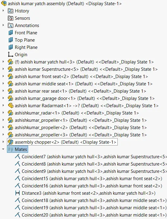
1. Then fix the Hull part by applying the coincident mate to the Top, Right and Front planes of the Assembly and Hull respectively.
2. Then for each part apply the necessary mates required by the Blueprint using Coincident mates, Angle Mates, Distance mates etc.
3. Advanced mate was also used wherever required.
RENDERING
It's a simple-to-use interface and provides an interactive environment for viewing designs as well as for creating photo-realistic renderings that can be used to showcase your designs. PhotoView 360 allows you to create a rendering within the SOLIDWORKS window.
PhotoView 360 is a visualization and rendering solution included with SOLIDWORKS. Providing a highly interactive environment for viewing designs as well as for creating photo-realistic renderings it can be used to showcase our designs.
PhotoView 360 is a software package, separate to Solidworks, which generates digital lifelike images (photorealistic images) from SolidWorks files. PhotoView 360 is an easy and quick way to produce high quality photorealistic images.
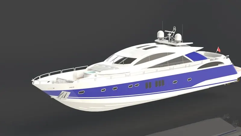
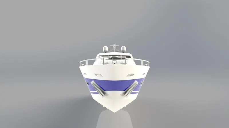
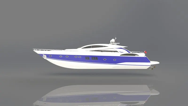
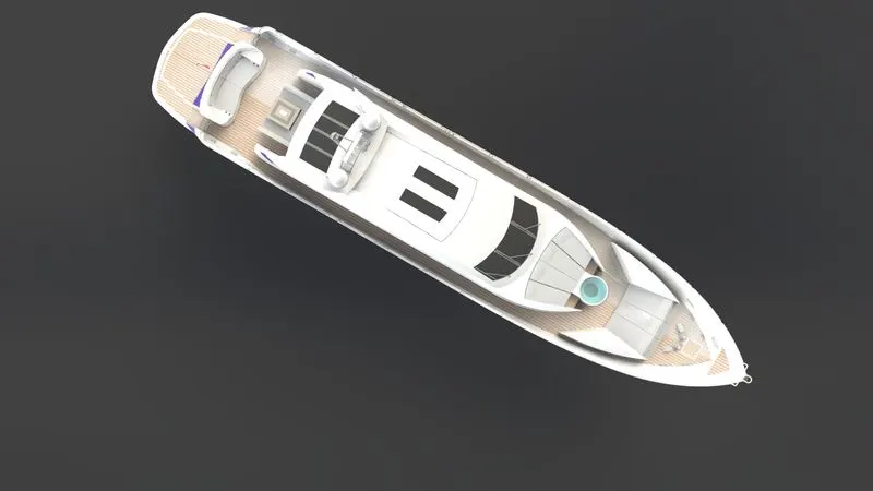
Environments - Environments can be looked upon as backdrops and can be applied in a similar manner as the appearances are applied to faces or parts
Appearances - There are a wider range of appearances in PhotoView 360 thanh SolidWorks. If we wish to change an appearance just drag and drop the chosen appearance onto the part and it will replace the existing one.
1. Lighting - Lights may be added in the same way a photographer adds lights when taking photographs PhotoView 360 uses the same lights as SolidWorks but also uses lighting from the rendering environment or scene. PhotoView 360 has the sophistication to trace light rays and reflections.
2. Scenes - Each SolidWorks model is associated with a PhotoView 360 scene, for which you can specify properties such as environments and backgrounds. Scenes help to put products in context.
3. Decals Images, such as company logos, can be applied to models.
4. Output - The rendered output from PhotoView 360 can be viewed on the screen, or saved to a graphics file. Options PhotoView 360 has its own options. Options allow you to customize the PhotoView 360 settings to reflect your preferences. Options are divided into Output Image Settings, Render Quality, Bloom, Contour Rendering and Direct Caustics.
SOLIDWORKS Visualize
SOLIDWORKS Visualize (formerly known as Bunkspeed) provides a suite of standalone software tools that combine industry-leading rendering capabilities with visual design-oriented features and workflows, allowing easy and fast creation of visual content that communicates a design's vision, passion, and emotion.
Quickly and easily create professional, photo-quality images, animations, and other interactive 3D content to get your products to market faster.
SOLIDWORKS Visualize allows us to leverage our 3D CAD data to create photo-quality content in the fastest and easiest way we can-from images to animations, interactive web content, and immersive Virtual Reality. It brings our products to life. SOLIDWORKS Visualize is the "camera" for our CAD data.
Some renderers are fast but output low-quality images. Some produce great quality but take six months to learn. Others are easy to use, but take four hours to render an image. SOLIDWORKS Visualize provides the right combination of quality, speed, and ease of use, and is the best renderer.
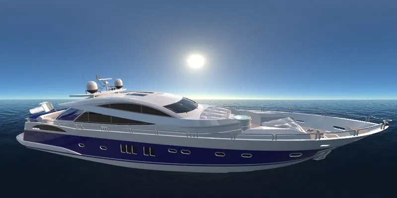
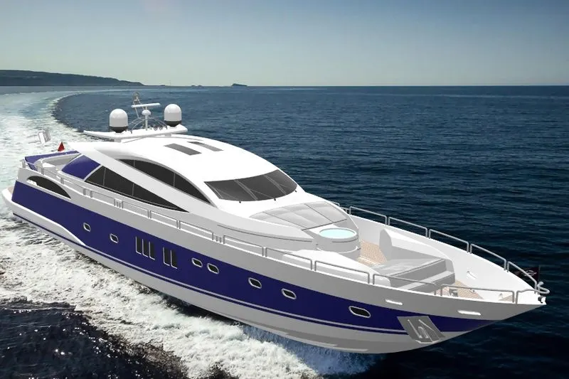
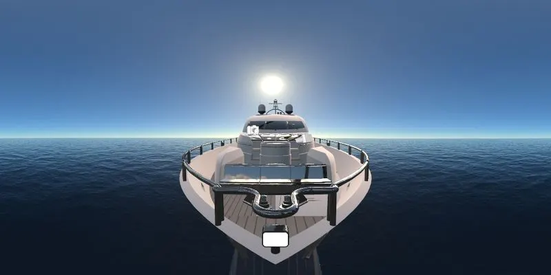
Render Queue
Similar to a printer queue, stack up render jobs to send all at once, for example at the end of the day, to remain productive during work hours and allow all the renders to cook overnight. The integrated Render Queue instantly boosts productivity allowing us to never wait for a render to finish again.
Procedure for creating visualization
With its simple, intuitive user interface, SOLIDWORKS Visualize requires virtually no learning curve and ter users produce content quickly. Even non-technical staff can start creating amazing content instantly.
• Create new project by importing the required assembly or models into the Solidworks Visualize
• Add the required appearance, environments, backplates and lights
By using the camera tool position the designed model in a realistic view
• Make sure that the model touches the floor. It can be achieved by using snap to the floor option on Models
By applying the required settings the required outputs can be rendered using output tool.
CONCLUSION
Thus the project design assembly and photo -realistic rendering of yacht was modelled and rendered succesfully.