Week 8 - Challenge 4 - Bumper
BUMPER:
A bumper is a structure attached to or integrated with the front and rear ends of a motor vehicle, to absorb impact in a minor collision, ideally minimizing repair costs.
OBJECTIVE:
The objective of the project is to design the PUMBER and to do a draft analysis for it by creating the required tooling direction with the help of Bisecting method.
MATERIEAL SELECTION :
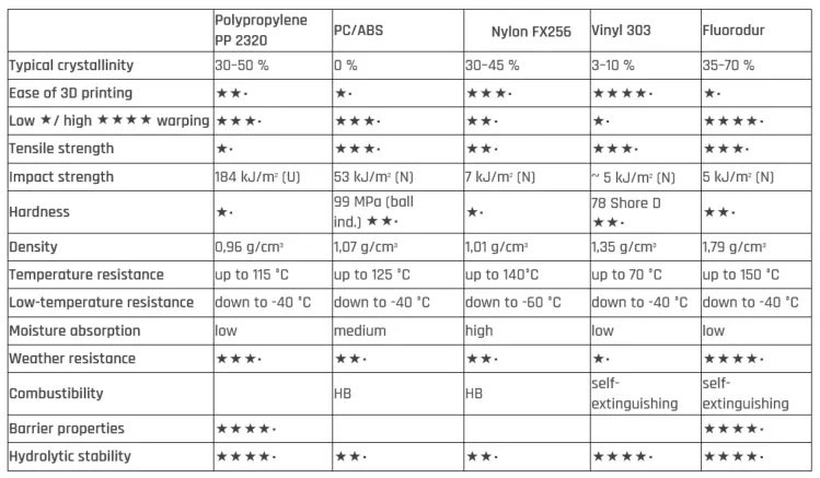
Material:Polypropylene.
*polyurethane is stronger than ABS plastic. And, yes, it can stand up better to high-heat environments. But in a real-world consumer
* Polypropylene is used the most frequently of any plastic in automotive manufacturing. Being a thermoplastic polymer, it can easily be formed into almost any shape
Key Properties of pp:
- High rigidity.
- Good impact resistance, even at low temperatures.
- Good insulating properties.
- High surface brightness and excellent surface aspect
TOOLING AXIS :
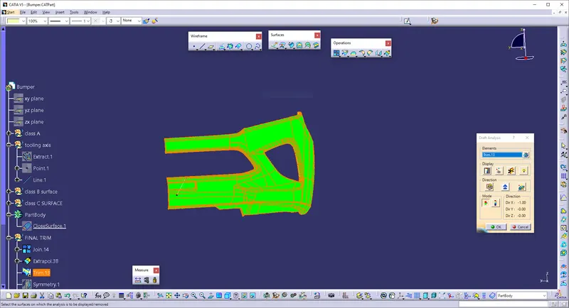
*The direction in which the mold or core and cavity opens is the tooling axis
- Considering the Ejection from the cavity of the mould after manufacturing the interior trim (switch bezel) must have the nominal 3-degree draft angle.
- Hence the tooling direction is created by considering the above factor and bisecting method is used.
CLASS A SURFACE:
Class-A (or 'Strak') is a term used in specifically in automotive design. It describes the final production surface data for the aesthetic parts of the car.
The Class-A modeling process typically starts with a fully developed design, either as a scanned clay model or an Alias model. Because the design isn't changing, the modeler has the time to build surfaces to the highest quality standards, ready for production.
The challenge for Class-A is to combine the need for:
- Aesthetic Quality – Continuity and Highlights
- Engineering Requirements – Flanges and Fit
CLASS B SURFACE :
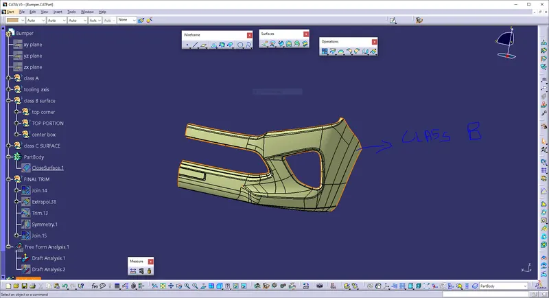
CLASS-B SURFACE: the class-B surface is the second surface that has a certain thickness from the class-A surface. this surface contains engineering aspects of a model. These must be smooth and "error-free" as well but are not held to the standards that class A surfaces are.
The Class B finish is a quality finish with only minimal imperfections. A Class B finish is the most common finish for exterior surfaces. It is normally specified on surfaces such as external covers, panels, and parts that are fairly prominent
CLASS C SURFACE:
The Class C finish allows more imperfections than Class A or B. Class C is often specified for interior
surfaces not readily visible, surfaces that will be covered by another part when assembled, or surfaces.
Draft analysis of A surface :
* the draft analysis based on the tooling axis
*The draft analysis technique is used to analyze whether our part model created in CAD is manufacturable based on the draft condition applied. Here the part should get easily removed from the panel dies
final draft analysis :
- First the class – A surface is checked before creating the Class –B&C surface and finally the solid body must be analysed. Both can be done by following the below procedures.
- By changing the view mode to custom view parameters – Material mode then the feature draft analysis is enabled.
- Then the compass was activated and placed with the tooling axis by dragging the red pointer and then locked it.
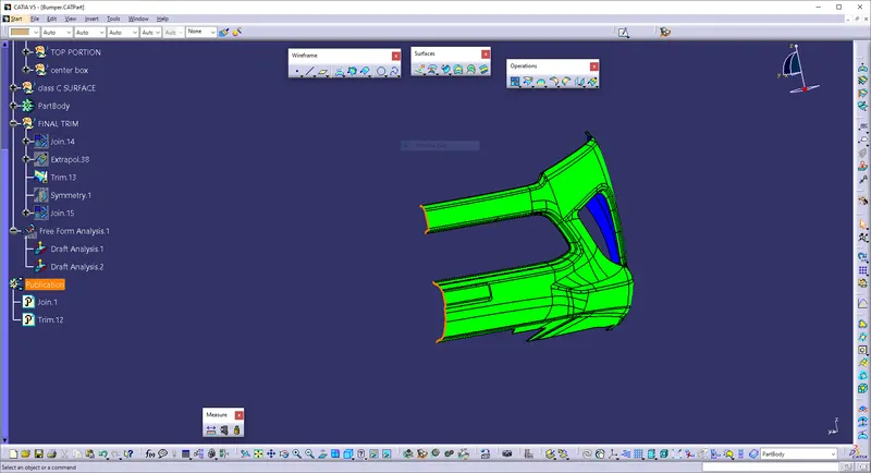
- Then, by selecting the quick analysis mode, the nominal value will be 3 degrees and checked for the component's draft angle.
- The green colour area shows that it satisfies the 3-degree draft angle. If not satisfied then by using the Running point tool the area is measured and then altered to get a successful draft for the created tooling direction.
conclusion
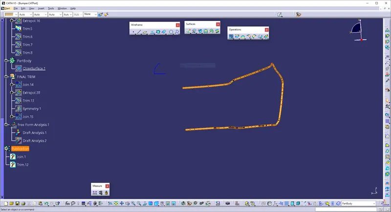
Finally the Class – A, B&C surfaces with the Tooling Direction have been Published and the BUMBER is moved on to the designing of the next operation – the creation of B-side features.