Week 8 - Challenge 4 - Bumper
AIM:
Create the Bumper Plastic component through the given Class-A surface. To begin with, the tooling axis for the given Class-A Surface should be created meeting the requirements of the draft angle and at the end perform the Draft analysis on the model.
Take the Thickness of the component to be 3 mm
MATERIAL USED:
Fiberglass is a common type of fiber-reinforced plastic using glass fiber. The fibers may be randomly arranged, flattened into a sheet called a chopped strand mat, or woven into glass cloth. The plastic matrix may be a thermoset polymer matrix—most often based on thermosetting polymers such as epoxy, polyester resin, or vinyl ester resin—or a thermoplastic.
Cheaper and more flexible than carbon fiber, it is stronger than many metals by weight, non-magnetic, non-conductive, transparent to electromagnetic radiation, can be molded into complex shapes, and is chemically inert under many circumstances. Applications include aircraft, boats, automobiles, bath tubs and enclosures, swimming pools, hot tubs, septic tanks, water tanks, roofing, pipes, cladding, orthopedic casts, surfboards, and external door skins.
Other common names for fiberglass are glass-reinforced plastic (GRP),glass-fiber-reinforced-plastic (GFRP). Because glass fiber itself is sometimes referred to as "fiberglass", the composite is also called fiberglass-reinforced plastic (FRP). This article will adopt the convention that "fiberglass" refers to the complete fiber-reinforced composite material, rather than only to the glass fiber within it.
APPLICATIONS OF FIBERGLASS:
Fiberglass is an immensely versatile material due to its lightweight, inherent strength, weather-resistant finish and variety of surface textures.
The development of fiber-reinforced plastic for commercial use was extensively researched in the 1930s. It was of particular interest to the aviation industry. A means of mass production of glass strands was accidentally discovered in 1932 when a researcher at Owens-Illinois directed a jet of compressed air at a stream of molten glass and produced fibers. After Owens merged with the Corning company in 1935, Owens Corning adapted the method to produce its patented "Fiberglas" (one "s"). A suitable resin for combining the "Fiberglas" with a plastic was developed in 1936 by DuPont. The first ancestor of modern polyester resins is Cyanamid's of 1942. Peroxide curing systems were used by then.
During World War II, fiberglass was developed as a replacement for the molded plywood used in aircraft radomes (fiberglass being transparent to microwaves). Its first main civilian application was for the building of boats and sports car bodies, where it gained acceptance in the 1950s. Its use has broadened to the automotive and sport equipment sectors. In the production of some products, such as aircraft, carbon fiber is now used instead of fiberglass, which is stronger by volume and weight.
Advanced manufacturing techniques such as pre-pregs and fiber rovings extend fiberglass's applications and the tensile strength possible with fiber-reinforced plastics.
Fiberglass is also used in the telecommunications industry for shrouding antennas, due to its Radio frequency permeability and low signal attenuation properties. It may also be used to conceal other equipment where no signal permeability is required, such as equipment cabinets and steel support structures, due to the ease with which it can be molded and painted to blend with existing structures and surfaces. Other uses include sheet-form electrical insulators and structural components commonly found in power-industry products. Because of fiberglass's lightweight and durability, it is often used in protective equipment such as helmets. Many sports use fiberglass protective gear, such as goaltenders' and catchers' masks.
PROCEDURE:
The steps involved in creation of this project are:
1. Bringing the class A surface of the switch bezel in Catia v5 software
2. Determining the tooling axis for the switch bezel
3. Creation of class B surface
4. Creation of class C surface
5. Joining all the class A, class B and class C surfaces of the switch bezel
6. Building closed surface after joining all the surfaces
7. Draft analysis on the switch bezel.
Tooling axis :
It is defined as the direction in which the molds opens or core and cavity, with the help of tooling axis created along x and Y axes are used for creating the Main Tooling axis by using bisecting method.
Procedure for creating Tooling Axis:
A Reference Point is created along the Surface zero and new Axis system is created
The X Direction along the Class A and Y direction along the Class A were used to create Tooling direction
Finally the Tooling axis is created by bisecting the two lines and it is published. Class A Surface as input using surface operation commands Class B is developed
The tooling Axis determines the direction of Class C boundary swept with draft direction.
When viewing from tooling direction normal all the parts that are drafted should be visible so it gives an rough idea to determine product manufacturing in Injection molding.
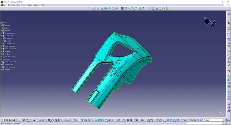
Draft:
A draft angle is a slant that is applied to each side of most features of an injection molded part. In other words Draft is providing tapers on the product features such as walls ribs posts and bosses that lie parallel to the direction of the release from the mold part ejection.
The nominal draft is 3mm for plastic components and for automotive sheet metal components is 7mm.
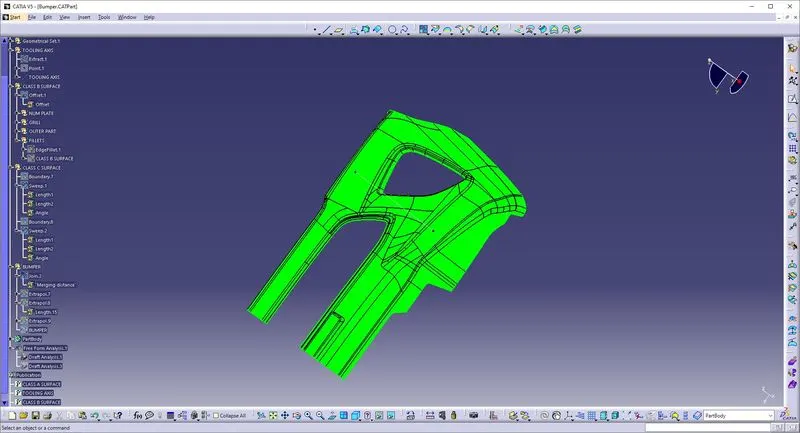
Class A:
Class A surface is the term mainly used in automotive design industry. It describes the final production surface data for the aesthetic parts of the car.
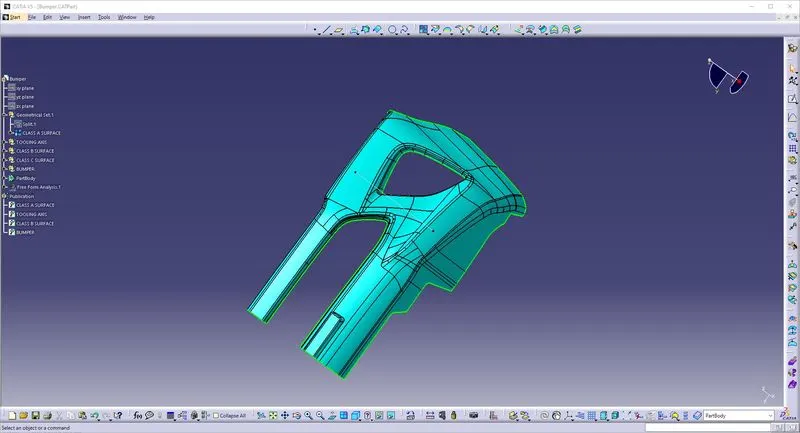
Class B:
Class B surface is the secondary surfaces which is not visible normally. These must be smooth and "error-free" as well, but are not held to the standards that class A surfaces are.
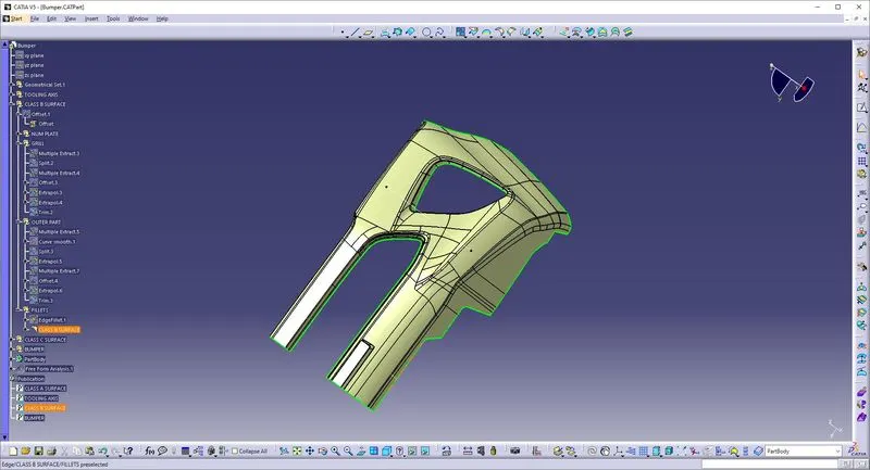
Class C:
Class C surfaces are the backside surfaces that can have tool marks, flash and other imperfections without hurting appearance, function, etc..
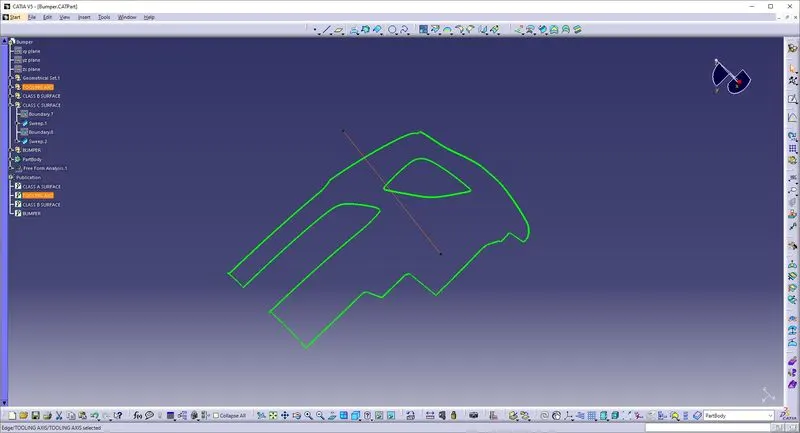
Creating a closed surface and forming a solid part from it:
Use the Trim Tool to form a closed surface from B-Surface and C-Surface.
Create a solid part from this closed feature using the Surface based feature in part workbench.
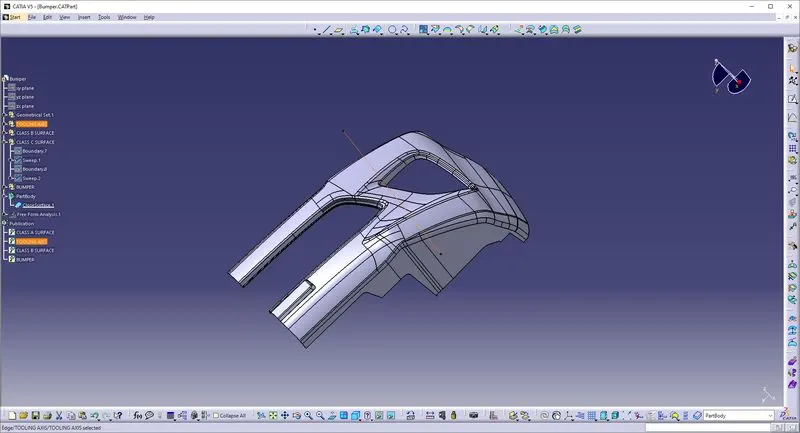
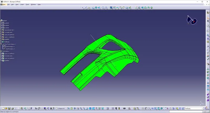
Draft Analysis of Solid Part:
Following the similar steps performed for draft analysis of Class-A surface we obtained the following result.
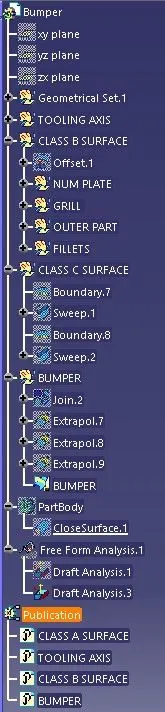
TREE STRUCTURE:
Conclusion:
Created the Bumper Plastic component through the given Class-A surface. To begin with, the tooling axis for the given Class-A Surface has been created meeting the requirements of the draft angle and at the end performed the Draft analysis on the model.