Week 8 - Challenge 4 - Bumper
Week 8 - Challenge 4 - Bumper
OBJECTIVE
- To Create or Develop Class B and Class C Surfaces of Bumper from the given Class A Surface.
- To Determine the Tooling Axis for the component.
- To Analyse Bumper by featured Draft analysis in Catia V5
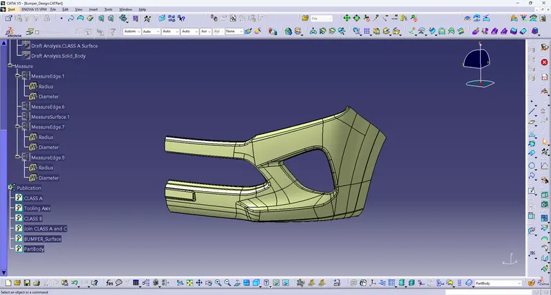
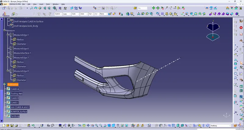
- Shown Screenshot is given Class A surface from the Design consideration team.From the surface create a centre point of the surface and add axis system from the point.
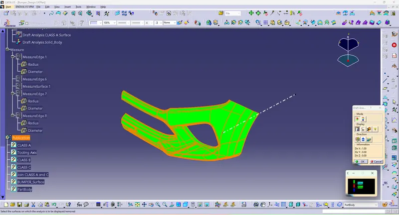
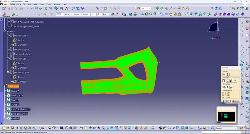
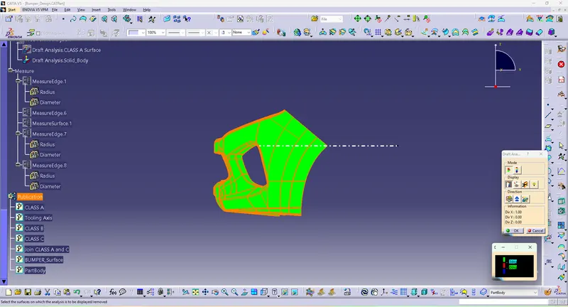
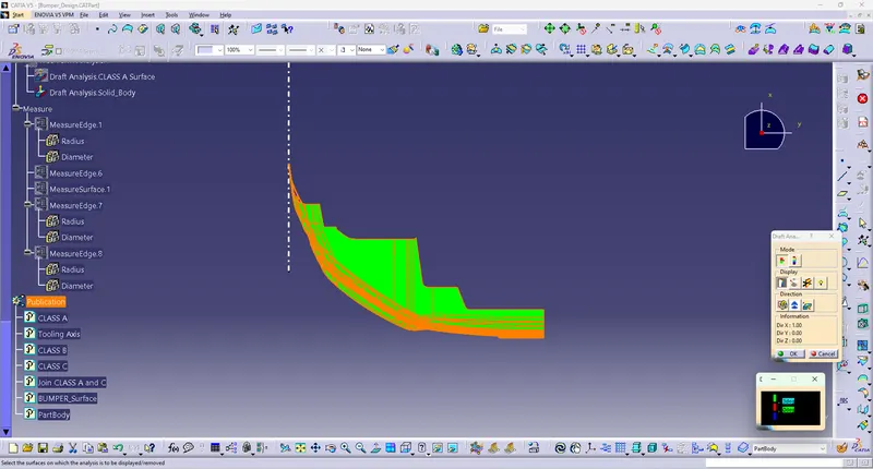
- I determine the possible tooling axis is X Direction.and also analyse on this axis by featured Draft analysis of the Class A surfaces.
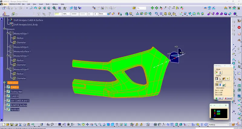
Screenshot of CLASS A Draft analysis at X Direction
- By analysis shown a resultant, X direction is a posssible Tooling axis.
CLASS B Creation
- By offsetting the Class A surface at 3mm distance (Because component thickness is 3mm).
- Somewhere surface section are break by offset the surface
- where, sections are broke are reconstruct by using Extract, Untrim and Extrapolate features
- then Combine those section to the Offset surface.
- After the Class B surface as Created
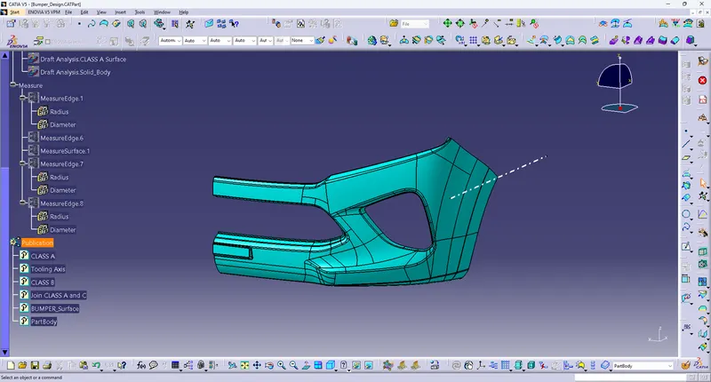
Screenshot is shown as CLASS B surface
CLASS C Creation
- From the Class A surfaces using Boundary command to all edges of the surface
- then sweep those section by define by reference surface with guiding of boundaries
- sweep at the angle of 90 degree at distance of 5mm
- then one sweep to another edges are extrapolate 2mm and trim those edges.
- after that join all Sweep section of the surface and considered as Class C surfaces.
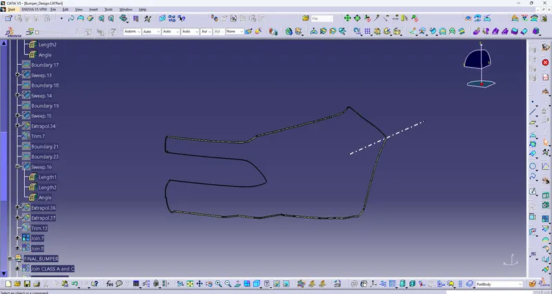
Screenshot of CLASS C surface
FINAL Bumper Creation
- Join Class A and Class C surfaces
- Then Trim Class B and Join of (Class A and C surfaces).
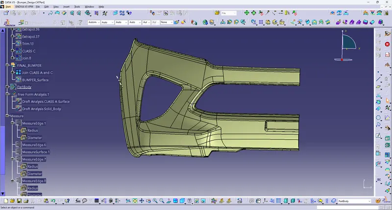
Screen shot of JOIN both Class A and C surfaces
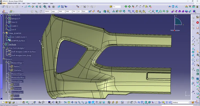
Screenshot of Trim of Class B and Join (Class A and C surfaces)
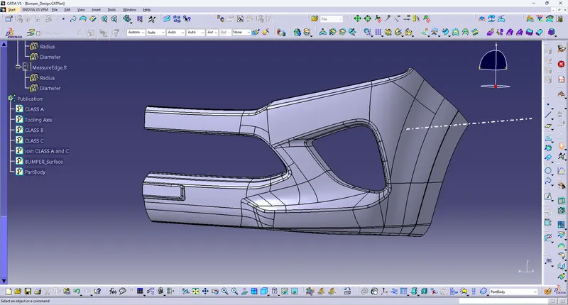
Draft Analysis
Class A Surface
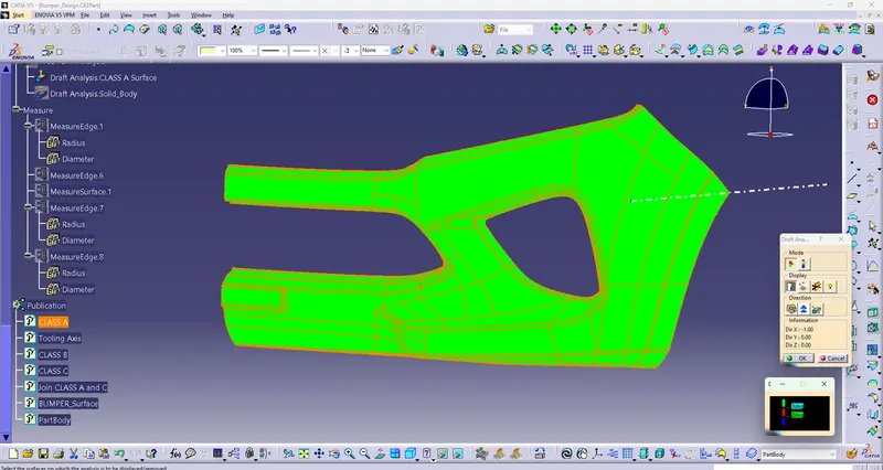
PartBody
Isometric View
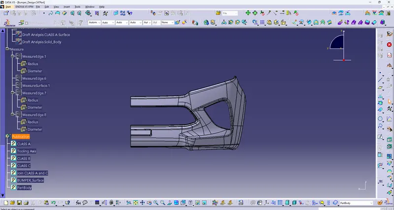
Front View
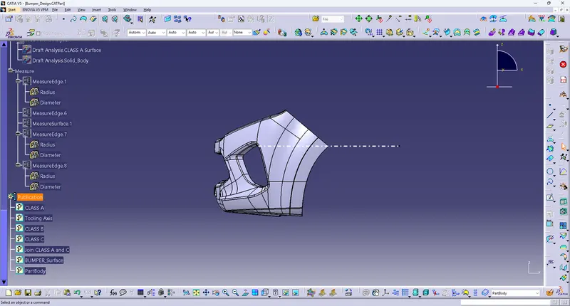
Side View
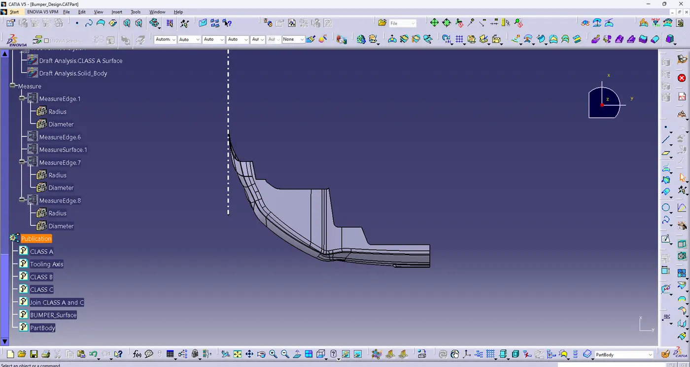
Top View
Part Body