Week 8 - Challenge 4 - Bumper
BUMPER DESIGN – CHALLENGE 4
AIM
Create the Bumper Plastic component through the given Class-A surface. To begin with, the tooling axis for the given Class-A Surface should be created meeting the requirements of the draft angle and at the end perform the Draft analysis on the model.
INTRODUCTION
A bumper is a structure attached to or integrated with the front and rear ends of a motor vehicle, to absorb impact in a minor collision, ideally minimizing repair costs.
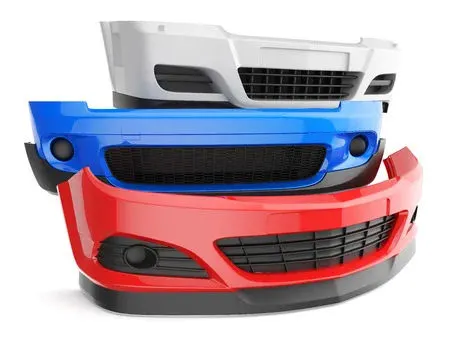
They are designed to absorb impact to the front and rear of vehicles and minimize low-speed collision damage. Today, standard passenger vehicle bumpers have a rigid reinforcing bar under the outer cover, with sections of compressible foam or plastic underneath.
A bumper is made up of four parts:
- Bumper cover.
- The bumper absorber.
- The bumper reinforcement bar.
- The bumper mounting system.
The first car bumpers were created all the way back in 1901 and consisted of metal beams attached to the front and rear of the car to protect it during a low-speed collision. Designed to protect the expensive and fragile components like the headlights, tail lights, hood, exhaust, and cooling systems, early metal bumpers were focused on sheer resilience.
Modern consumer production cars have almost completely switched over to plastic bumpers. Modern car bumpers are made from thermoplastic olefins, a blend of plastic molecules, rubber, and a reinforcing filler like carbon fiber or calcium carbonate. This blend of materials creates a scratch and impact-resistant plastic that can bond with a wide range of paints and finishes, making it ideal for vehicle bumpers.
Plastic is the preferred material for modern car bumpers for several reasons. First and foremost, plastic is much lighter and more aerodynamic than metal, which improves the car's fuel efficiency. Plastic is also easier to shape, which is useful during both the manufacturing and bumper repair process.
Bumpers of most modern automobiles have been made of a combination of polycarbonate (PC) and acrylonitrile butadiene styrene (ABS) called PC/ABS.
OBJECTIVE
- To design Bumper as per automotive industry Standard.
- Create tooling axis for the given CLASS-A surface.
- Create B Class and C Class surfaces
- Create final surface model and convert it into solid body using close surface command in the part design workbench.
- Perform draft analysis for both Class-A surface and Final part body.
DESIGN METHODOLOGY
Skin data would be provided to us by the styling team to us.
Class-A surface means visible surface. It gives the aesthetic of the component which is created by the styling team and gives to the part design engineer to create the part with all engineering aspects.
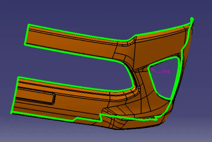
The first step is to check the continuity of the class A surface. This is to ensure that there is no gap between surfaces. If we find any then we should fix that first.
Class-A continuity check
Analyse the class A surface through visual inspection.
To make sure that the given surface has no gap in between them. We can check it also with the help of Join or boundary commands.
Procedure for creating the tooling axis
Tooling axis represents the opening and closing of the mold core and cavity during the manufacturing of the components. A plastic product designer should consider the best tooling direction to cutdown the cost of the component very less.
Method opted for creating tooling axis for the bumper
- Check the best tooling direction for the given surface.
- We can find out the best tooling direction by cross checking all the three axes.
Draft analysis for the given CLASS-A surface
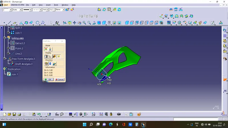
The Draft Analysis is a command enables you to detect if the part you drafted will be easily removed. This type of analysis is performed based on colour ranges identifying zones on the analysed element where the deviation from the draft direction at any point, corresponds to specified values.
Draft analysis is done after determining the tooling axis, draft analysis is used to check whether the minimum draft (3 degrees) is maintained or not.
- Procedure for performing the draft analysis are as follows
- Change the view mode of the component to be in customized parameter mode and then select the shading mode as materials.
SURFACE-B CREATION
Class-B surface means thickness of a part it is not visible and is inside part. In other words, Class-B surface is a surface below a certain thickness from the class-A surface. This is the surface that contains engineering aspects of a model.
- Offset the class-A surface to 3mm inward direction.
- Rework on the patches and discontinuity of the offset surfaces using the features like extract, multi-extract, sweep, multi-section surfaces, extrapolate.
- To ensure the continuity of the Class-B surfaces check the boundary command to find out the boundary.
- Hence class-B surface creation is done.
SURFACE-C Creation
Surface that joins class-A and class-B surfaces is class-C surface. Class C is often specified for interior surfaces not readily visible, surfaces that will be covered by another part when assembled
Since it is a complex class-A surface, we cannot simply create the class-A boundary curve and sweep it at one shot. Hence, we need to create smaller curves using multi-extract command and then create sweep of 90 degree with reference to the surface option. sweeps at the midportion of the bumper should have a 93 degree vaue to pass the draft analysis.
.
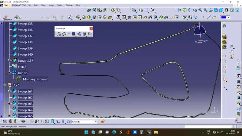
Creating the final surface of Bumper
- First step is to join the CLASS-A surface with CLASS-C surface.
- Then Trim the Joined surface with CLASS-B surface to achieve the final Bumper surface.
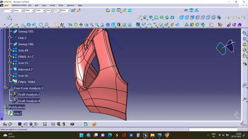
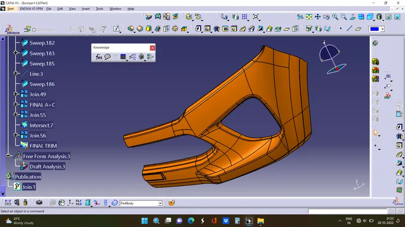
Go to the part design work bench and using the close surface command create the base bracket solid part body
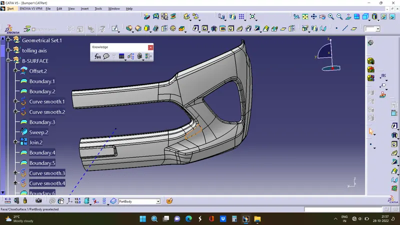
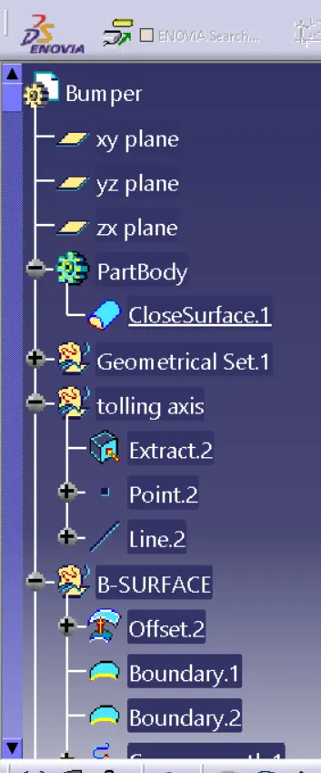
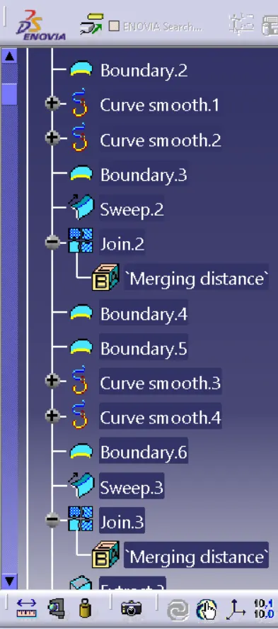
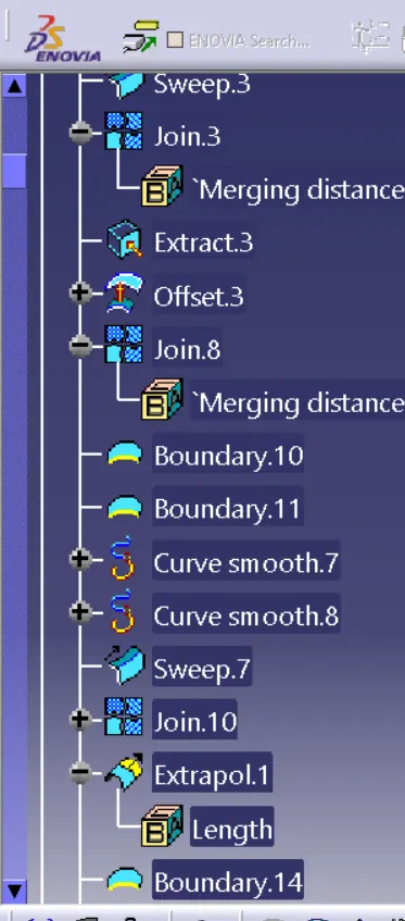
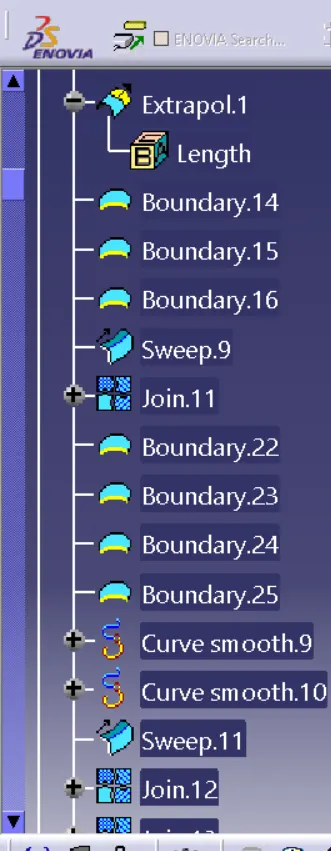
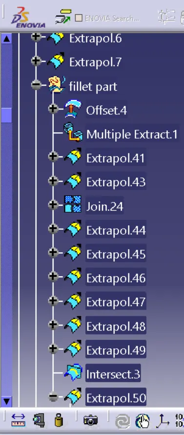
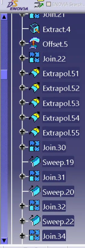
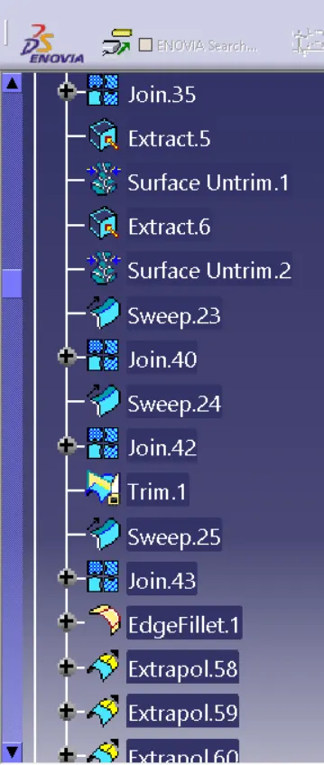
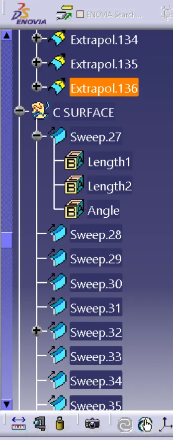
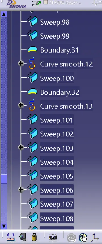
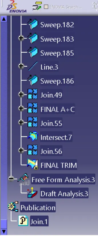
The expanded Tree Structure for the geometrical set and the Part Body
conclusion
I have successfully created the class-B and Class-C surfaces of Bumper using the given Class-A surface along with the tooling axis in the CATIA surface workbench.