Week 8 - Challenge 4 - Bumper
BUMPER DESIGN
BUMPER DESIGN – CHALLENGE 4
AIM
Create the Bumper Plastic component through the given Class-A surface. To begin with, the tooling axis for the given Class-A Surface should be created meeting the requirements of the draft angle and at the end perform the Draft analysis on the model.
INTRODUCTION
A bumper is a structure attached to or integrated with the front and rear ends of a motor vehicle, to absorb impact in a minor collision, ideally minimizing repair costs.
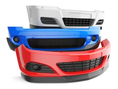
They are designed to absorb impact to the front and rear of vehicles and minimize low-speed collision damage. Today, standard passenger vehicle bumpers have a rigid reinforcing bar under the outer cover, with sections of compressible foam or plastic underneath.
A bumper is made up of four parts:
- Bumper cover.
- The bumper absorber.
- The bumper reinforcement bar.
- The bumper mounting system.
The first car bumpers were created all the way back in 1901 and consisted of metal beams attached to the front and rear of the car to protect it during a low-speed collision. Designed to protect the expensive and fragile components like the headlights, tail lights, hood, exhaust, and cooling systems, early metal bumpers were focused on sheer resilience.
Modern consumer production cars have almost completely switched over to plastic bumpers. Modern car bumpers are made from thermoplastic olefins, a blend of plastic molecules, rubber, and a reinforcing filler like carbon fiber or calcium carbonate. This blend of materials creates a scratch and impact-resistant plastic that can bond with a wide range of paints and finishes, making it ideal for vehicle bumpers.
Plastic is the preferred material for modern car bumpers for several reasons. First and foremost, plastic is much lighter and more aerodynamic than metal, which improves the car's fuel efficiency. Plastic is also easier to shape, which is useful during both the manufacturing and bumper repair process.
Bumpers of most modern automobiles have been made of a combination of polycarbonate (PC) and acrylonitrile butadiene styrene (ABS) called PC/ABS.
OBJECTIVE
- To design Bumper as per automotive industry Standard.
- Create tooling axis for the given CLASS-A surface.
- Create B Class and C Class surfaces
- Create final surface model and convert it into solid body using close surface command in the part design workbench.
- Perform draft analysis for both Class-A surface and Final part body.
DESIGN METHODOLOGY
Skin data would be provided to us by the styling team to us.
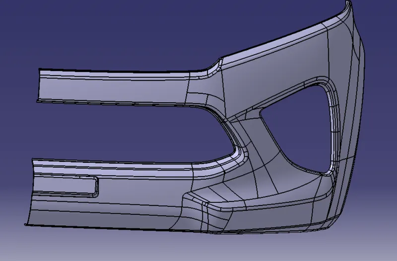
Class-A surface means visible surface. It gives the aesthetic of the component which is created by the styling team and gives to the part design engineer to create the part with all engineering aspects.
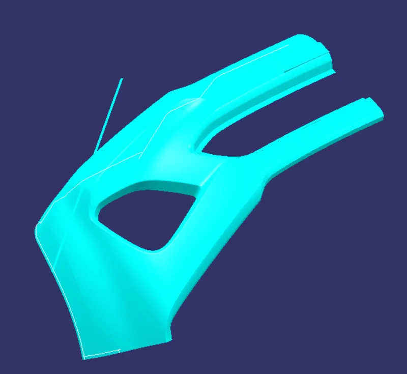
Given Class A:
The given Class A is joined together to avoid patches in the class A surface.
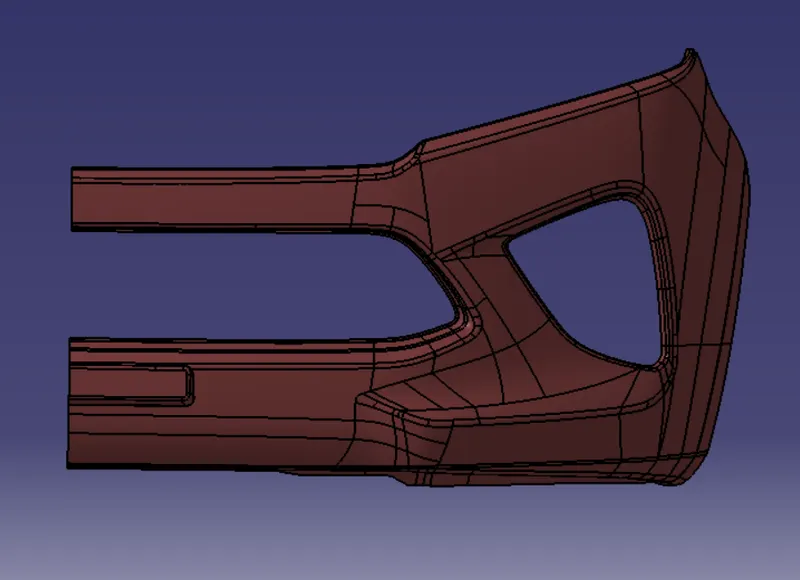
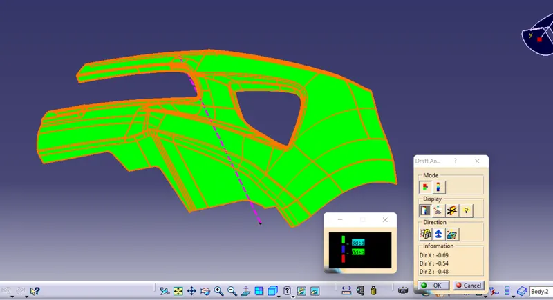
Creation Of Tooling Axis & Draft Analysis On Class A:
A point is created on the class A surface and a line is created on through the point.
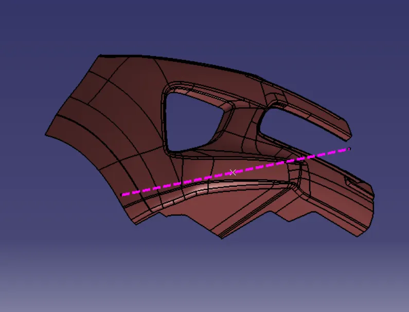
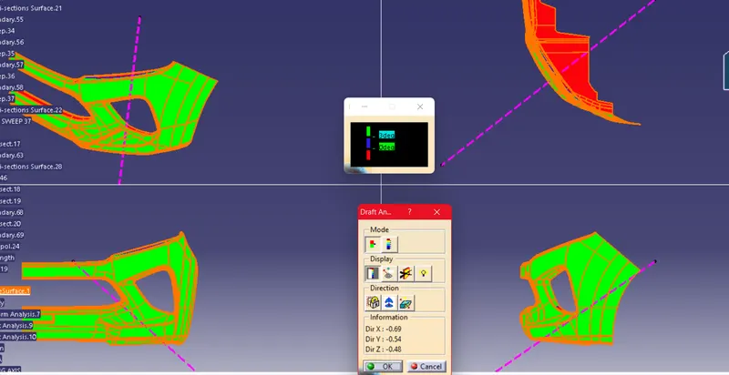
and Draft analysis is performed.
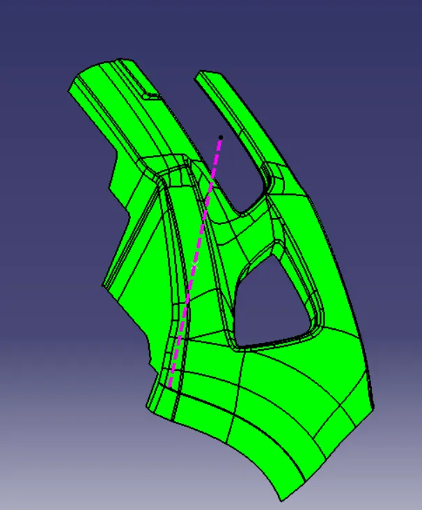
Creation Of Class B:
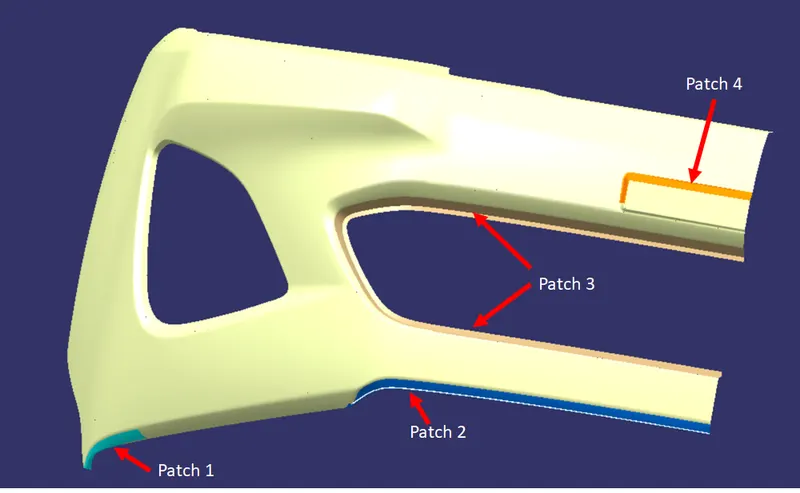
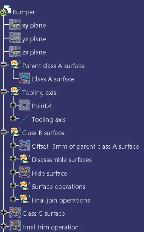
The Class A is offsetted 3 mm and there are some patches on the offsetted surface.
Taking Boundaries,Multi section Surface,Extrapolation,Multiple extract etc those patches are resolved.
Creation Of Class C and AC:
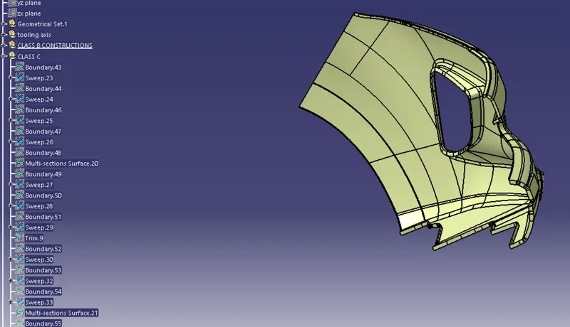
Class C is created by taking the boundary of Class A and taking the multiple extract of it and by using sweep.
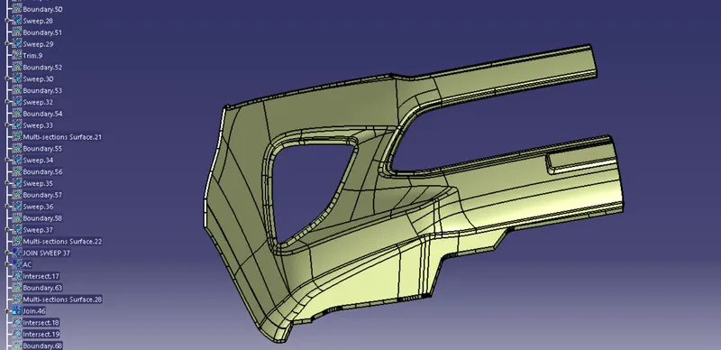
And the class C is joined with A surface and AC surface is created.
Final Solid Body:
Using close surface in part workbench the final plastic Body is Created.
Draft Analysis:
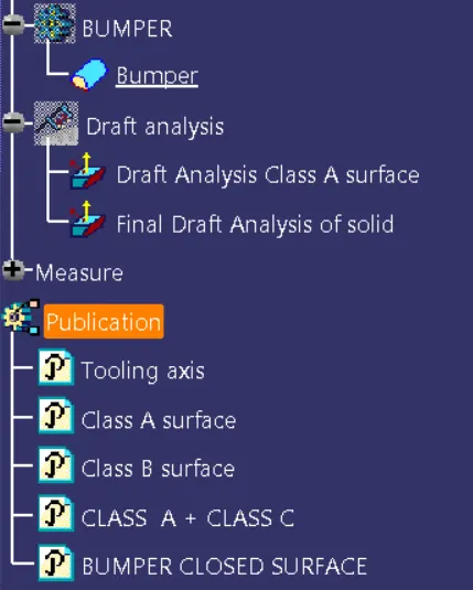
Tree structure
Conclusion:
The Bumper Plastic Component is created from Class A and Draft analysis Is performed.