Week 8 - Challenge 4 - Bumper
TOOLING AXIS:
Tooling axis is the direction in which the core and cavity opens. If we are using proper tooling axis, we can avoid adding side cores thus the cost of manufacturing the component can be reduced.
It is defined as the direction in which the mould/core and cavity open. Selection of the direction of the tooling axis depends on the ease at which components can be easily ejected.
Generally tooling axis is decided from the natural axis of the design, that is, tooling axis is analysed with the x, y and z axis of the system. If the axis doesn’t clear the draft analysis, the next step is to look for the surface in which the drafting axis can be created in such a way that the axis is normal to the surface taken. These are the methods of deciding tooling axis. Bisecting method is the least used method.
DRAFT ANALYSIS:
From draft analysis, we can verify draft angles, examine the angle changes within a face, as well as locate parting lines, injection and ejection surfaces in parts.
It is an important feature in Catia which helps the user to analyse the draft on various surfaces. The draft analysis toolbar provides two modes for analysis of the draft, first is the quick analysis which basically has three colours (green, red, and blue) for analysing on the other hand other option is the full analysis mode which enables a few more details into the draft and is used in the complex components.
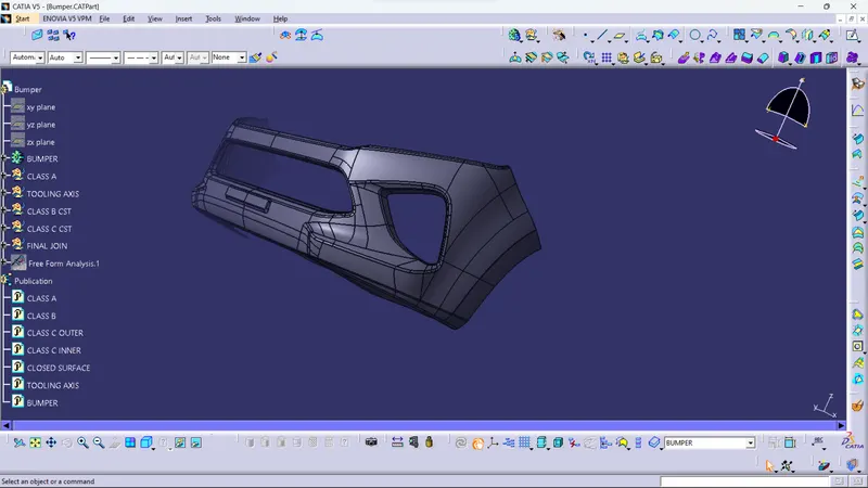
Draft analysis of class A
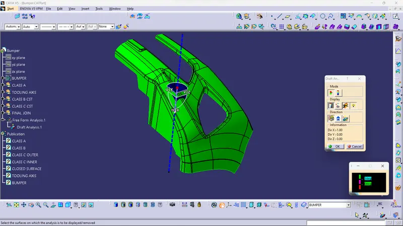
Draft analysis of FINAL PLASTIC COMPONENT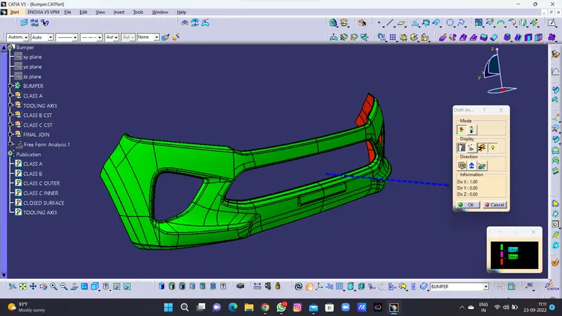
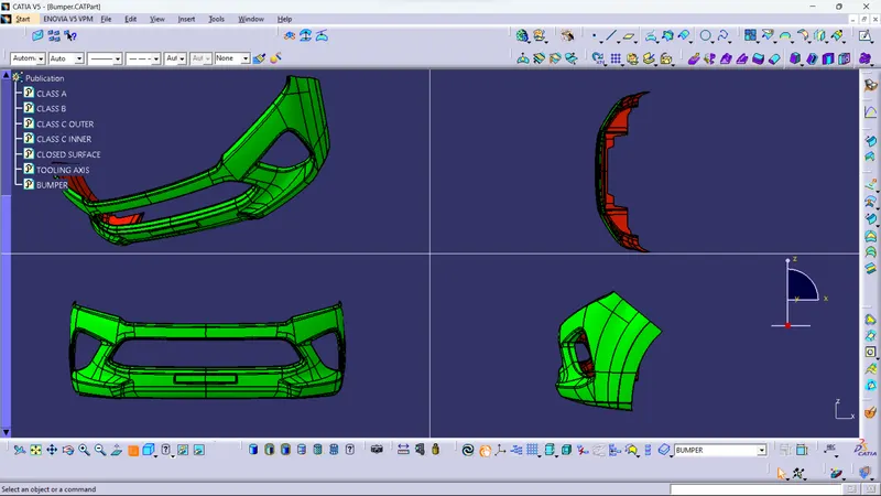
Screenshots of the solid model with the proper color code of the draft angle in various orientations (Isometric, Front, Side, and Top View)