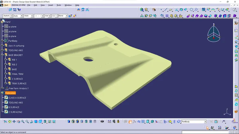
Week 8 - Challenge 1 - Base Bracket Design
TOOLING AXIS:
- Tooling axis can be classified into two methods
- direct method
- bisecting method:
- In this model we use bisect method based on the requirement. This method is used for complex components.
- To use boundaries and make bisect the lines for creating a tooling axis
- To ensure the class-A surface is properly joined and has no discontinuity to it.
- To Analyze the surface for to setup tooling axis based on best suitable angle and direction.
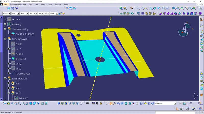
- A point was created at the center of the large circle, Using that axis system is inserted,
- Using the yz plane an intersection is to be made.
- Two lines need to be created from the points-take any two of the incline lines as reference,
- Create a bisecting line for the inclination lines,
- The tooling axis is the tool movement axis (core/cavity).
- This axis will decide the draft direction.
-
Draft analysis
- Draft allows for the component to release from the mould, most parts or applications require a minimum of 0.5 to 1 degree draft angle and 3 dgree draft angle is widely used as per the norm.
- Change the material mode to customize mode before moving to the draft analysis.
- Insert –analysis-feature draft analysis
- Defining the draft direction Select draft analysis from the tool bar and click on the compass symbol and pull the compass from the right side top corner of the workbench and place it on the component where want to do the draft analysis. ‘W’ of the compass and tooling axis should be aligned on the same line.
- By clicking the on the surface and using the flipping tool we can assign the Flipping direction .
- Click on the lock symbol and click on the component then a table will appear it shows the draft value.
- Analysis under running point and move the mouse on the surface and it will show the details of the surface deg direct.
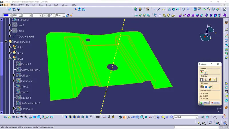
The above picture is the result of the draft analysis of class A surface
The draft is considered as 3 degrees.
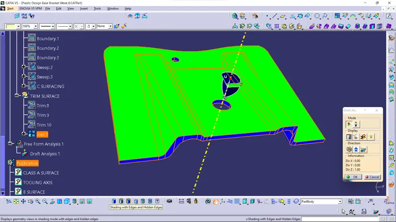
The above picture is the result of the draft analysis of final plastic component surface
The draft is considered as 3 degrees.
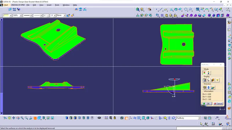
creenshots of the solid model with the proper color code of the draft angle in various orientations (Isometric, Front, Side, and Top View)