Week 8 - Challenge 4 - Bumper
Report:
Objective:
Is to design the Plastic model to pass the feasibility check to avoid the manufacturing error.
Tooling Axis:
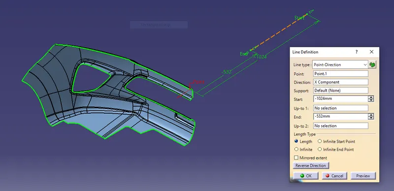
Tooling axis is created to show the tooling direction which show the movement of the Mold and cavity & to exit the part without damaging the surface.
Tooling axis is created alomg the x axis direction.
Why X direction?
Because in x axis direction i can find the total surface is visible to me. During the draft analysis it will clear in all surface.
Draft Analysis:
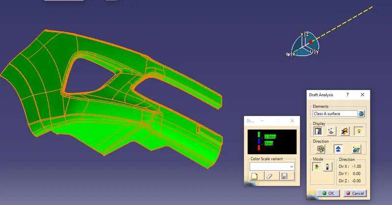
Draft Analysis for Class A Surface:
- Click the draft analysis command in analysis toolbar.
- Positioned the compass in the tooling axis.
- Activated the compass in draft analysis dialogue box.
- Again repositioned the compass in the tooling axis.
- Clicked the Class A surface.
- Here green color is given for surface clearing the draft angle of 2.9 and above.
- Here it clear in all surface. there is no defects in Class A surface.
Creating of Solid model:
Step 1:
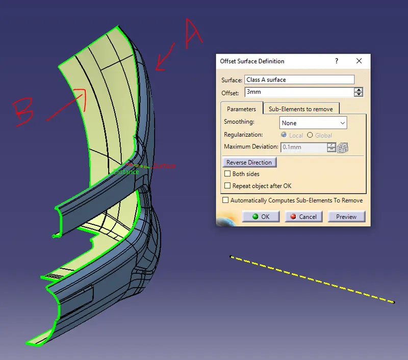
Creating of Class B Surface:
- Class B surface is created for the given offset value of 3mm.
- In three areas the fillet got failed. In number plate, Grill, Top position.
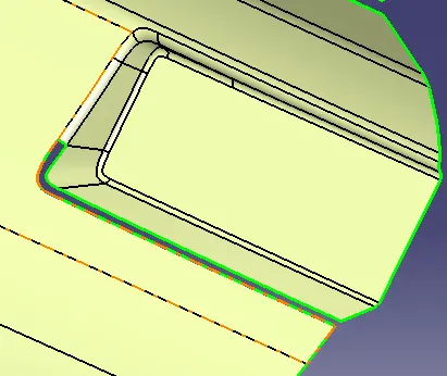
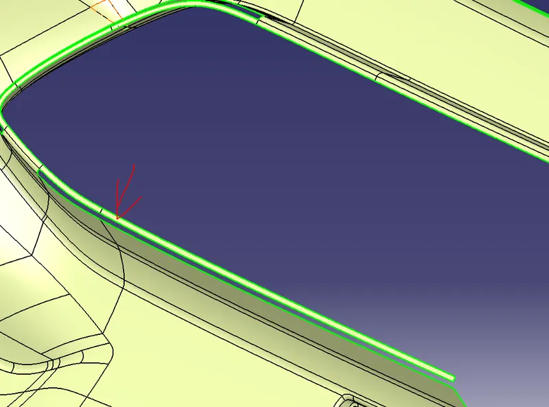
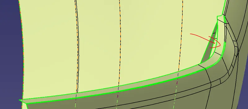
Command used to repair the fillet area:
- Boundary
- Multiple extract
- Extrapolate
- Multi section surface
- Join(Sub-elements to remove)
- Trim
- Split
- offset
- Edge Fillet
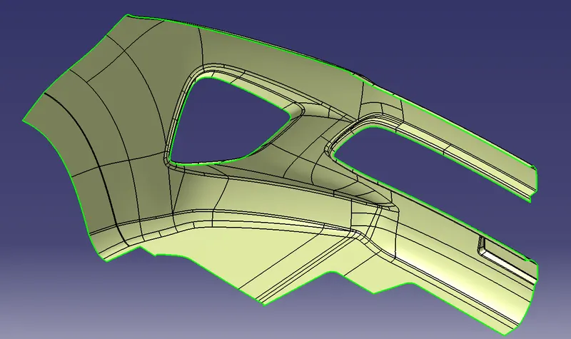
Step 2:
Creating of Class C surface:
Class c surface is created between the Class A & B surface. This surface which act as connecting surface. Class C Surface is created from the Class A Surface using the sweep command with referance surface option. Creating the Class C surface plays major role which created According the draft angle to avoid the falling of parting line in the Class A Surface. The C surface is created outward from the Class A surface.
According to the class C surface the Class B surface is extrapolated to merge with the Class C surface.
Class C surface draft angle is given about 3 degree
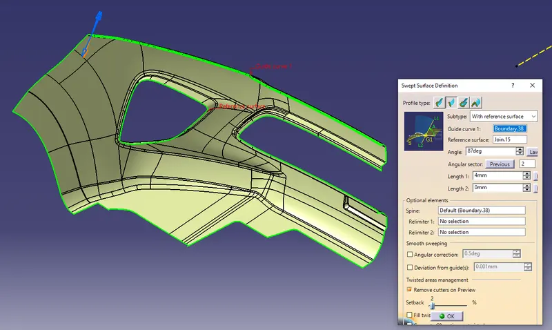
Command used to create the Class C surface:
- Boundary
- sweep
- Extrapolate
- Trim
- Trim the class C surface to get the closed surface.
- Class C Surface is Joined to the Class A surface.
- Class A&C joint is trimed with the Class B surface.
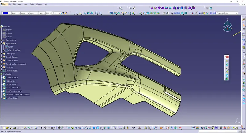
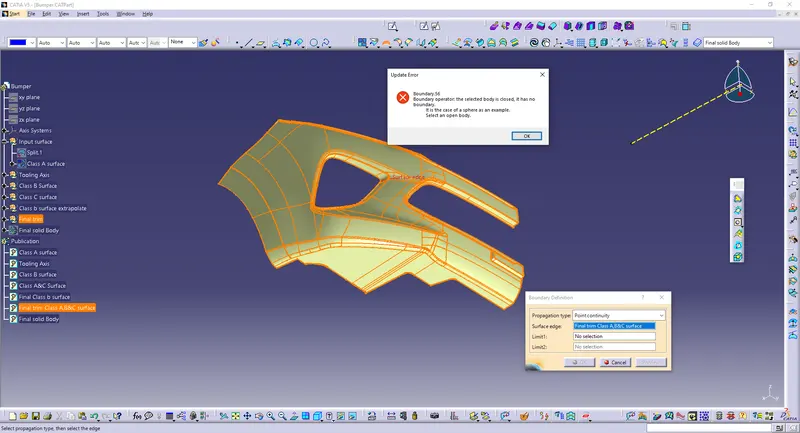
Verified the final surface trim has any boundary or nor.
By taking the boundary command and select the model.
It show the notification as - the selected body is closed, it has no boundary.
Step 3:
Creating of Solid model:
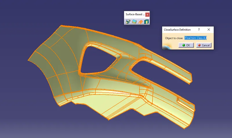
Switched to the part workbench.
Using Close surface command the surface model is converted into solid model.
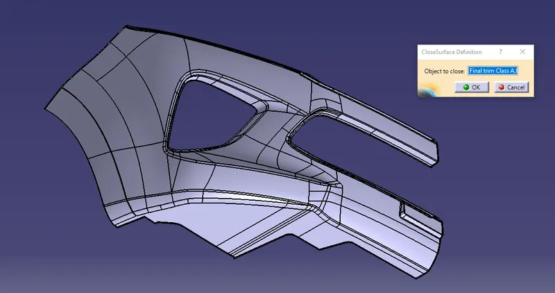
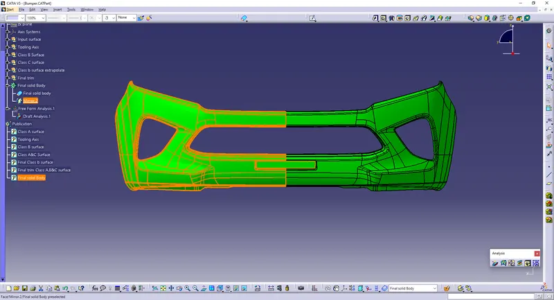
Then it is mirrored to achieve the full bumper.
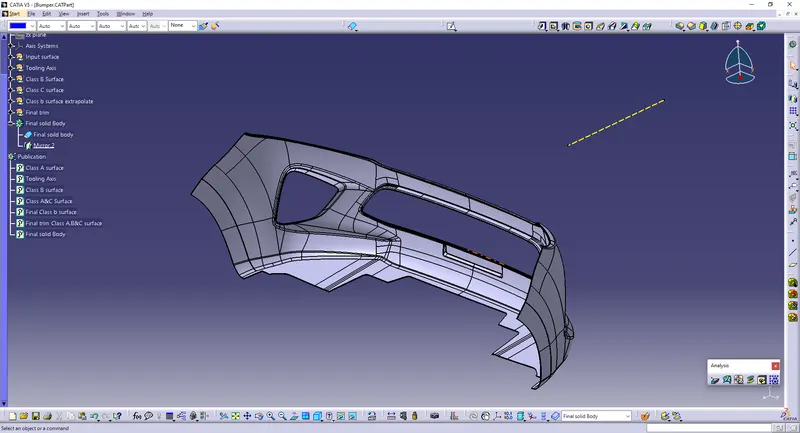
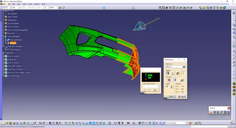
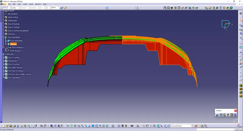
Draft analysis is performed for the final solid model:
- Click the draft analysis command in analysis toolbar.
- Positioned the compass in the tooling axis.
- Activated the compass in draft analysis dialogue box.
- Again repositioned the compass in the tooling axis.
- Clicked the solid model.
- Here green color is given for surface clearing the draft angle of 2.9 and above.
- Here it clear in all surface.