Design Car Bumper
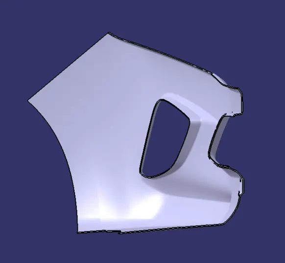
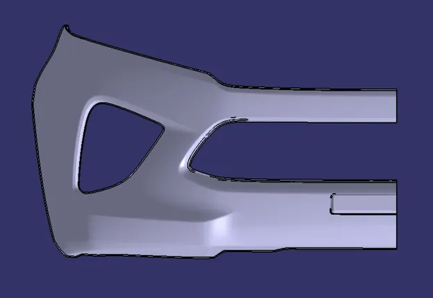
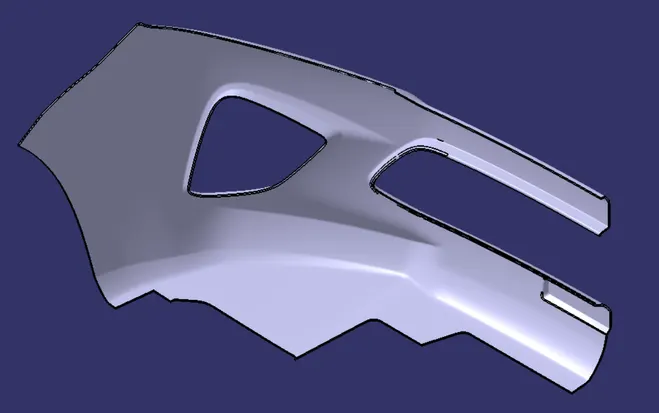
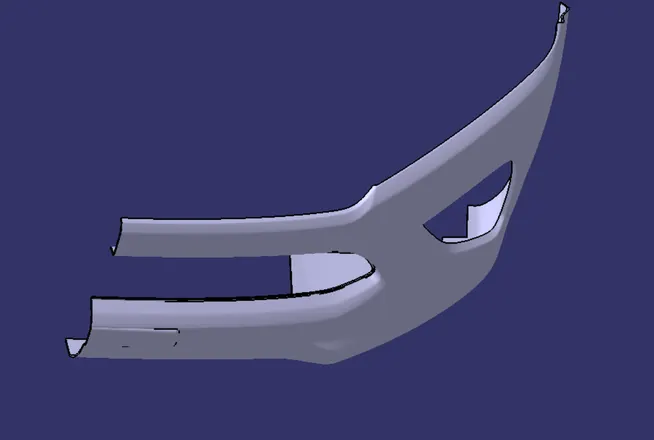
AIM:- To design a car bumper Plastic component through the given Class-A surface by creating a tooling axis and draft analysis of the given surface.
INTRODUCTION:-
CLASS-A SURFACE:- a surface made by the designer which is given as an input to the plastic modeler to work on. It is aesthetic surface
and the outer most surface.
CLASS-B SURFACE:- a surface below a certain thickness from the class-A surface is class-B surface. This is the surface that contains
engineering aspects of a model.
CLASS-C SURFACE:- a surface that joins class-A and class-B surfaces is class-C surface.
Tooling axis:- The direction in which the mold or core and cavity open is the tooling axis.
Tooling Direction:-
The Tooling Direction is basically the direction that the mold pulls apart. The mold is built in two separate pieces, basically. You have a Cavity side and you have the Core side. The Core pulls apart from the Cavity and that's the Dyeline or the Tooling Direction. There are different methods to find out the tooling direction. Here we are using bisecting method to find out the tooling direction. We can use any method the ultimate aim is to reduce the cost of manufacturing by reducing the complicity in manufacturing the component.
PROCEDURE:-
The first thing to do is to find out the possible tooling direction by visually checking the part. Rotate the part in all directions and find out the most suitable direction for tooling. Here in this case viewing from the Z direction we can clear the face in tooling.
Then we create a point on the surface of the part, we can create the point anywhere on the surface but usually, we take a CG point or take a point near to the center. At this point, we put a new axis system.
Then we are finding out the tooling axis in the X direction. For that intersect command is used to get the boundary in the X direction or XZ plane.
Extending the drafted face using a point-to-point line command. Then using bisecting line command bisect both extended lines to get the tooling axis in the X direction.
Since in Y direction there is no wall to create a bisect. We finalize the tooling axis in the X direction as the main tooling axis.
DRAFT ANALYSIS:-
First we analysis the model and then choose dummy axis in x and y direction.
As we intersected to proceed we observed that the side walls are not given any draft. Hence we assume the axis normal to the base surface and parallel to side walls. This surely will create problems because a minimum draft has to be provided.
As class-A surface is made by other designer only he is authorized to make changes, so we look over this to complete the coin holder for practice.
Now we go to insert< analysis< draft analysis and follow usual procedure to do the analysis.
Align the compass and click on the surface and as expected the model is mostly in red color i.e. negative draft with respect to the axis.
To correct it to as best as we can we moved the compass a bit till we got most of the surfaces in green and lock that position.
After hitting ok, we change the direction of the line from z axis to compass direction. The axis will align itself accordingly.
Parting Line:-
Where the core and cavity of the injection molding machine in that meeting point of the core and cavity is called parting . it is nothing but partition between the core and cavity
If the parting line is not in proper area it affects the class A surface
A parting line, in industrial casting of molds, is the border line in which draft angles change direction. One can check the parting line in the mould or product which divides the two half, i.e; the core and the cavity of a molded part. It is sometimes a starting point for the mold parting surface.
In this particular exercise class A surface is given as input
Class B and Class C surface should we have to do it properly with the correct draft angle.
And make the component as solid body.
And do the draft analysis of that component that we have made.
Process of Injection Molding:-
Overview and Characteristics Injection molding is a forming process using molds. Materials such as synthetic resins (plastics) are heated and melted, and then sent to the mold where they are cooled to form the designed shape. Due to the resemblance to the process of injecting fluids using a syringe, this process is called injection molding