Week 8 - Challenge 4 - Bumper
OBJECTIVE:
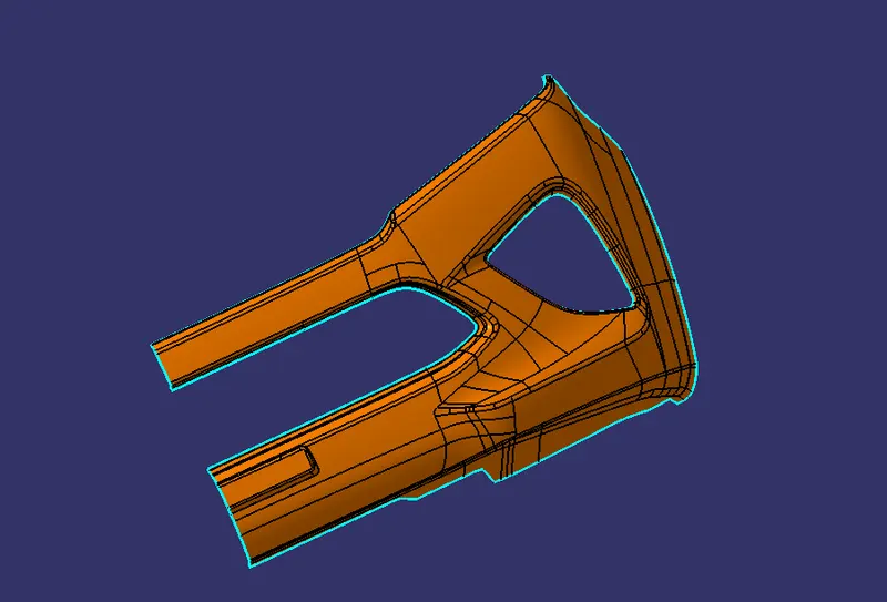
Create the Bumber Plastic component through the given Class-A surface.
To create the tooling axis for the plastic component
To perform draft analysis over the plastic component.
OVERVIEW:
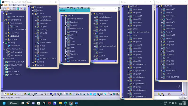
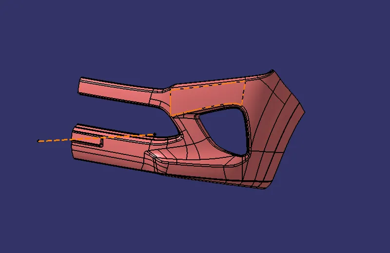
Initially, we need to offset the given Bumber class A surface in the inner direction to the required thickness (here the thickness is 3mm). After that, we need to close the patches on the offset surface of the bumber, the patches are formed due to the fillets on the Class A surface. Once all the patches are closed properly join them together to make a proper class B surface and now sweep the boundary of the class A surface then join to trim with the class B surface to make a closed body. By using the closed body command in the Prat workbench we can get the solid body from the closed surface of the Bumber. Now, again went back to the surface workbench to perform the Draft analysis for the solid body.
CLASS A SURFACE:
TOOLING AXIS:
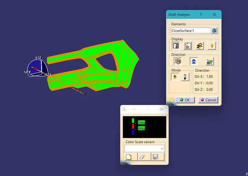
To create the tooling axis, I extracted a surface from class A and created a point in the middle of the surface by using the point command and created a line at that point through the x-axis. Now, I performed a draft analysis check from that line whether the created tooling axis is in the correct position or not. If in the draft, analysis check the surface highlighted with green colour on both sides of the surface the tooling axis is in the correct position and direction.
DRAFT ANALYSIS FOR CLASS A:
DRAFT ANALYSIS:
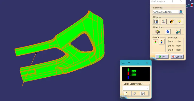
- First the class - A surface is checked before creating the class B&C surface and finally the solid body must be analysis. Both can be done by following procedures.
- By changing the view mode to custom view parameters -material mode then the feature draft analysis is enabled.
- Then the compass was activated and placed with the tooling axis by dragging the red pointer and then locked it.
- Then, by selecting the quick analysis mode, the nominal value will be 3 degree and checked for the component's draft angle.
- The green colour area shows thast it satisfies the 3- degree draft angle. if not satisfied then by using running point tool the area is measured and then altered to get a successful draft for the created tooling direction.
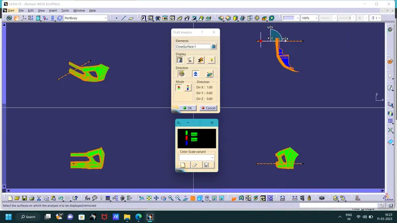
DRAFT ANALYSIS FOR BUMBER:
FINAL PART BOBY:
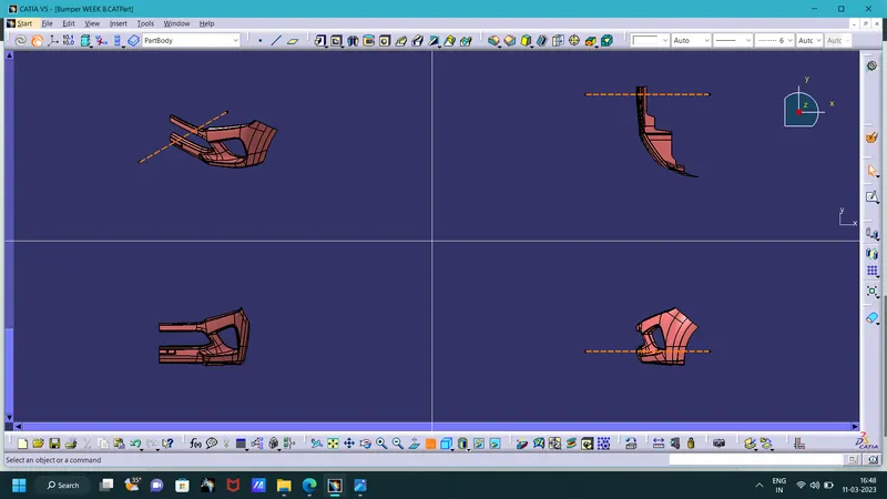
Isometric, Front, Side, and Top View:
TREE STRUCTURE: