Week 8 - Challenge 3 - Switch Bezel Design
Aim :
Create the Switch Bezel Plastic component through the given Class-A surface. To begin with, the tooling axis for the given Class-A Surface should be created meeting the requirements of the draft angle and at the end perform the Draft analysis on the model.
Note : Offset distance = 2.5mm.
Axis system :
Using Insert - Axis system axis on the extracted base surface is created which will be used in tooling axis creation.
Step 1 : Tooling Axis
Tooling axis for the given class A surface is created. In the below picture blue coloured dis continuous line defines the toooling axis. Generally tooling axis is generated for the drafted sides which may create the defects during the production. Defining Tooling axis is the important factor in injection moulding of plastic materials. Defects in plastic moulding include:
-
Flow Lines
-
Sink Marks
-
Vacuum Voids
-
Surface Delamination
-
Weld Lines
-
Short Shots
-
Warping
-
Burn Marks
-
Jetting
-
Flash .
Step 2 : Draft Analysis
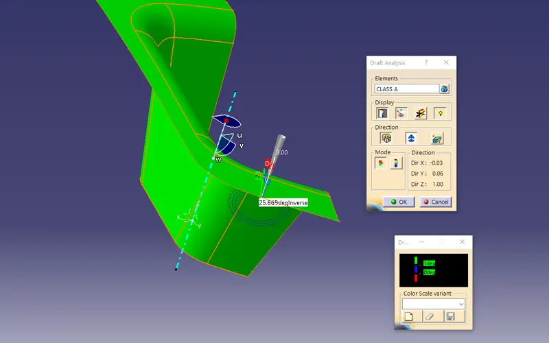
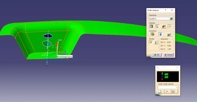
The Draft Analysis command enables you to detect if the part you drafted will be easily removed. This type of analysis is performed based on color ranges identifying zones on the analyzed element where the deviation from the draft direction at any point, corresponds to specified values.
Draft analysis for the given class A surface is done inorder to ensure the draft angle of the sides are 3 deg or more. Where Green colour indicates the positive draft angle, red colour indicates the 0 degree or no draft in the surface and Blue colour indicates the negative draft angle. Draft angle is another important factor in creating core and cavity.
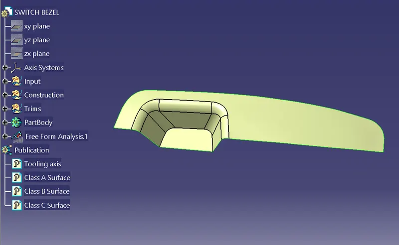
Step 3 : Class A surface
Class A surface is defined from the input Class A surface for the part design. Which is basically extracting the exact A surface from the IGES part. Generally Class A surface will be given for future plastic part production. Class A surfaces can be defined as any surface, that has styling intent, that is either seen, touched or both.
Step 4 : Class B Surface
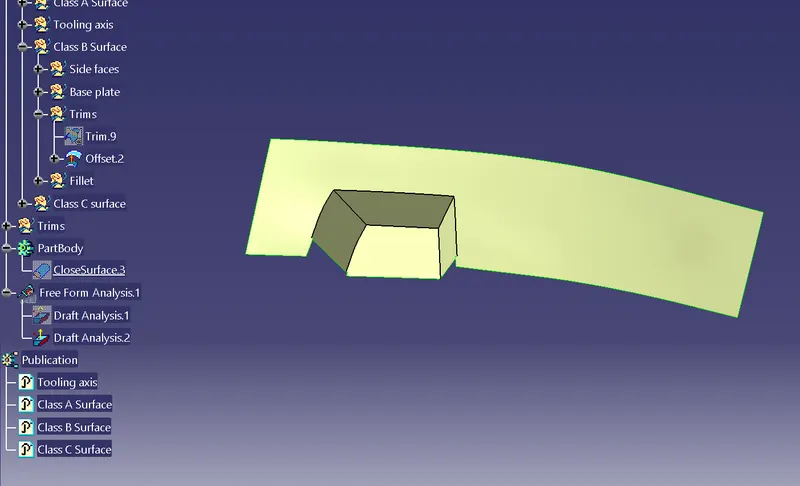
The Class B finish is a quality finish with only minimal imperfections. A Class B finish is the most common finish for exterior surfaces. It is normally specified on surfaces such as external covers, panels, and parts that are fairly prominent. Class B surface is extracted from the class A surface and is offsetted according to the tooling axis.
Generally Class B surfaces are known as bottom side surface or hidden surface of the solid part which will have negative draft angle with respect to the tooling axis.
Step 4 : Fillets
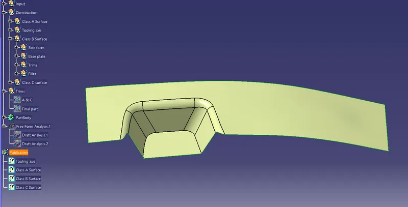
Fillets are added to the Class B surface. Generally, class B surface have fillets different radii from the class A surface. Which is determined based on the nature of the fillet , either concave or convex in nature.
For concave nature fillet, the offsetted fillet value will be the addition of the class A fillet radii and the off set distace. (eg : if the radius of the A surface fillet is 15mm and offset distance of the B surface is 3mm then, the fillet value will be 15+3 = 18mm.)
For convex nature fillete, the offsetted fillet value will be the difference in the value of the class A fillet radii and the offset distance.(eg : if the radius of the A surface fillet is 15mm and offset distance of the B surface is 3mm then, the fillet value will be 15 - 3 = 12mm.)
Step 5 : Class C Surface
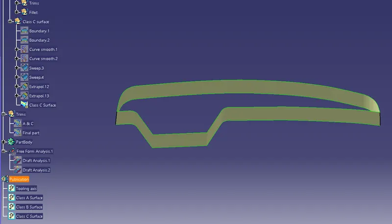
Class C surface is created by extracting the boundaries of the class surface. The outer boundaries are created for the given Class A Surface, then the the boundaries are checked for its continuity, and its nature of continuity.
The extracted boundaries are swept along the tooling axis with preffered draft angle which is generally 3deg, inwards or outwards based on the draft analysis.
The distance between each point of the edges of two neighboring patches must comply with the following limits:
• For class A: no more than 0.01 mm.
• For class B: no more than 0.02 mm.
• For class C: no more than 0.05 mm.
Tangents continuity
The angle between the tangents to the surface on the edges of two neighboring patches must comply with the following limits:
• For class A: no more than 6’ (0.1◦).
• For class B: no more than 12’ (0.2◦).
• For class C: no more than 30’ (0.5◦).
Curvature continuity
The control parameter is the patch curvature along its contour.
• Class A surfaces must have coincident curvature at least every 100 mm of
contour of two neighboring patches.
• Class B and C have no applicable rule.
Points of maximum curvature or inflection are only allowed along patch contours of Class A surfaces.
(Source from google)
Step 6 : Joining A & C surfaces
Extracted A & C srface are either trimmed or joined by defining new geometrical set naming Trims or operations, for future easy access.
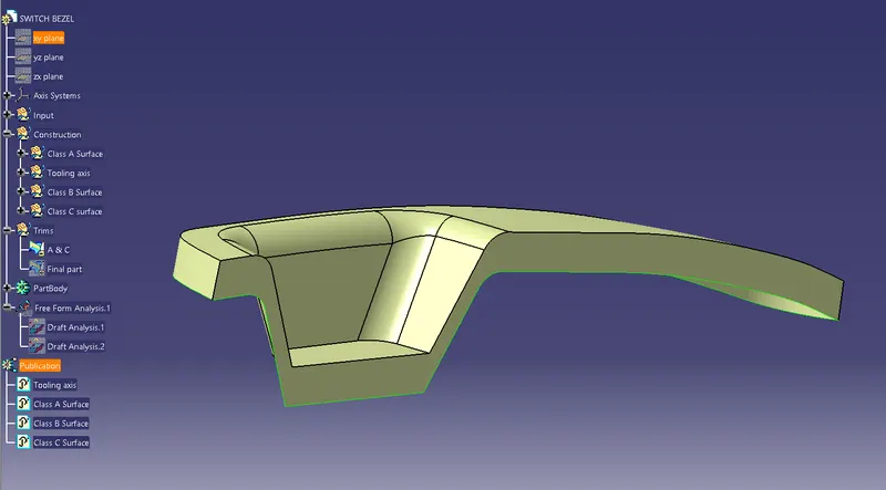
Step 7 :Trimming
The Class B surface is then joined with the A & C sides. This done either by trimming the parts or joining parts. Here, I have trimmed the B surface from A & C surface joint.
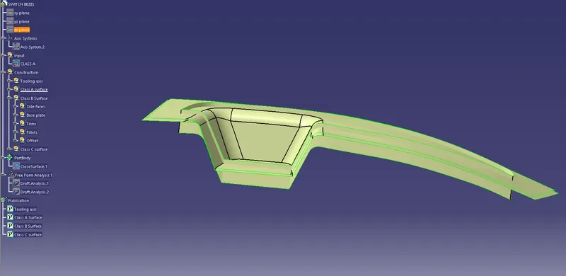
Final Surface design and Publication:
This picture shows the final surface design for the given Class A surface.
Before trimming the surface we must publish the tooling axis, Class A surface, Class B surface, and Class C surface for easy acces to the surface for further operations and also for production accebility.
(Tools - Publications - _ surfaces_).
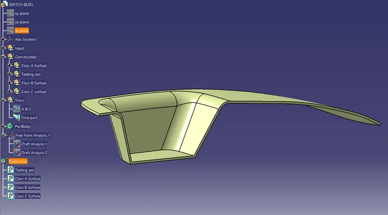
Step 8 : Solid Part design
Now the work bench is changed from surface design to part body work bench. Using the closed surface tool the surface design is converte to solid part. This closed surface tool will be availabe in the surface design toolbar (or surface toolbar).
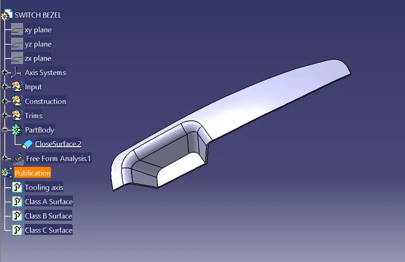
Views
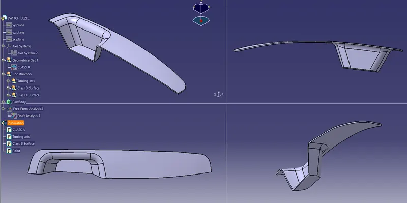
This below diagram shows the multiple side views of the generated part body.
Step 9 : Draft analysis of part body
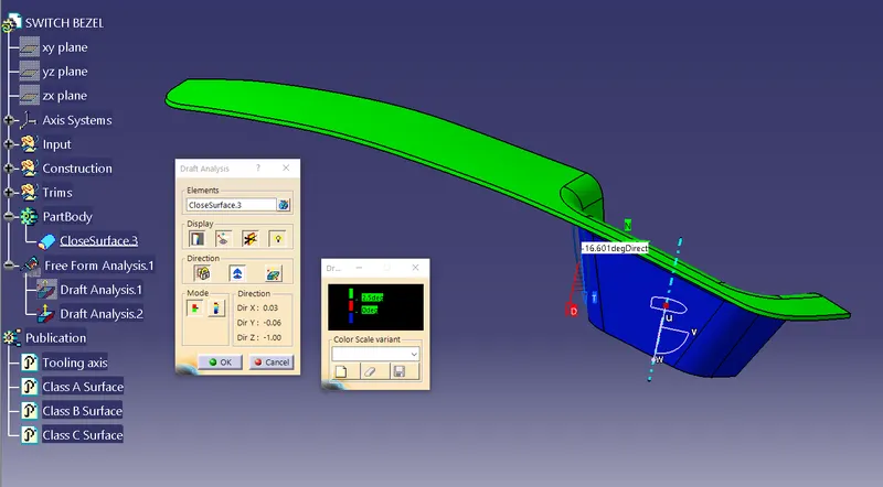
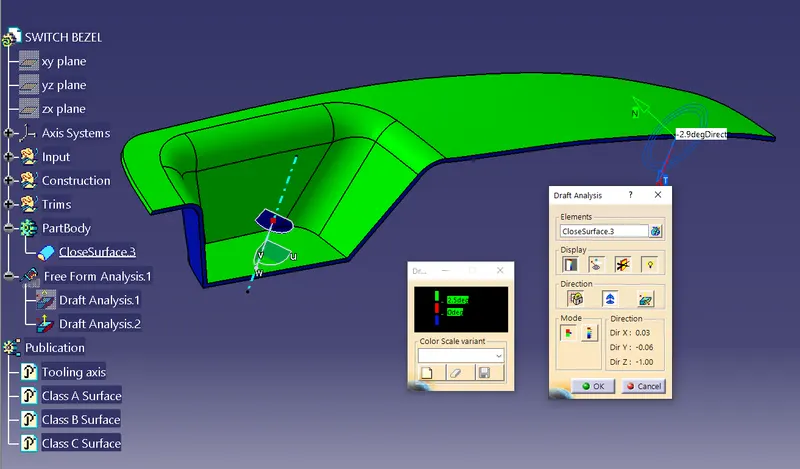
Previously draft analysis wss done for the given A surface. Now, draft analysis is done for the generated part body, whether part body aligns with the tooling axis. If the draft angle is more than 3deg it will show green colour, if it is less than 3degree analysis will show error result, it is also acceptable in certain parts.